
Manual


2
Warner Electric • 800-825-9050 P-201 • 819-0485
Contents
Installation Instructions
PB-120 PB-170 PB-250 PB-400 . . . . .2-9
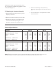
Electrical Specifications . . . . . . . . . . . . . . . . . . . .5
Drawings and Parts Breakdown or Exploded Views
PB-120 . . . . . . . . . . . . . . . . . . . . . . . . . .10-11
PB-170 . . . . . . . . . . . . . . . . . . . . . . . . . .12-13
PB-250 . . . . . . . . . . . . . . . . . . . . . . . . . .14-15
PB-400 . . . . . . . . . . . . . . . . . . . . . . . . . .16-17
Warranty . . . . . . . . . . . . . . . . . . . . . . .Back Cover
Follow the installation instructions in this
manual carefully to ensure safe, reliable
operation. All stated or implied manufacturer
warranties are void if this product is not
installed in accordance with these
instructions.
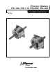
PB-170
PB-400
Primary Brake
PB-120 PB-170 PB-250 PB-400
The illustration drawings, parts lists, and
exploded views for these units can be found
beginning on page 10.
A. Installing the Conduit Box
To install the conduit box on the size 400 unit,
refer to the instructions supplied with conduit
box.
B. Mounting the Magnet
The brake magnet is mounted to a stationary
machine member by a flange. Extreme care
must be taken in selecting the location for the
mounting of the magnet. Proper positioning is
very important for the unit to function correctly.
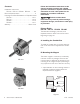
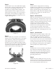
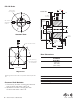
1. A pilot diameter on the mounting surface is
essential to hold the magnet within the
required tolerances (Figure 1).
Mounting
Surface
Magnet
Pilot
Diameters
Figure 1
Failure to follow these
instructions may result in product damage,
equipment damage, and serious or fatal injury
to personnel.