
Manual
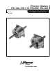


3
Warner Electric • 800-825-9050 P-201 • 819-0485
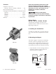
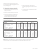
2. A machined pilot diameter is provided on the
magnet mounting flange (refer to illustration
drawings page 10-17) to aid in the proper
positioning of the magnet.
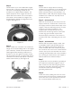
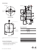
3. Once the mounting surface has been
prepared, the magnet is bolted in place with
capscrews and lockwashers. (Figure 2.)
4. After assembly, the magnet must be
concentric and square within the required
tolerances listed on the illustration drawing.
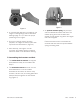
C. Assembling the Armature and Hub
1. The antibacklash armatures are shipped
assembled and ready to be installed. See
Step D.
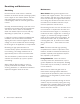
2. The standard armature and hub must be
assembled before it can be installed.
Assemble the armatures so that the shiny
surfaces (120 and 170) or backing plate sides
(250 and 400) are against the hub retainer
ring (Figure 3).
Figure 2
Figure 3
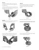
3. An optional release spring may be used
with the standard armatures and hubs. The
release spring forces the armature back
against the hub retainer ring when the magnet
coil is de-energized.
Follow these instructions to assemble the
armature and hub when the optional release
springs are being used.