
Manual


4
Warner Electric • 800-825-9050 P-201 • 819-0485
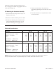
PB-170
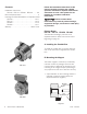
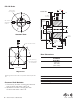
Assemble the splined armature to the hub. The
shiny side of the armature should be against the
hub retainer ring.
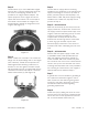
Assemble the release spring into the groove in the
hub spline. The curved portion of the spring should
be against the armature. (Figure 4)
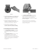
PB-250
Insert the hub, with snap ring intact, into the arma-
ture from the backing plate side. (Figure 5)
Insert both release springs into the holes of the
backing plate. Bow the springs as necessary to
insert them into the armature. (Figure 6)
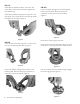
PB-400
Insert the release springs into the backing plate
holes of the armature. Bow the springs as
necessary to insert them into the armature.
(Figure 7)
Remove the snap ring from the hub.
Insert the hub, with the setscrew end first, into the
armature from the segmented side. Slide the hub
into the armature until the release springs engage
the snap ring groove. (Figure 8)
Figure 4
Figure 5
Figure 6
Figure 7
Figure 8
Figure 9