
Manual


5
Warner Electric • 800-825-9050 P-201 • 819-0485
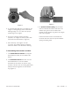
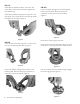
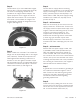
Assemble the snap ring into the groove in the
hub, clamping the release spring against the end
of the spline. (Figure 9)
D. Mounting the Armature Assembly
1. (250 and 400 units only) Insert a key in the
keyway of the shaft.
2. Slide the armature assembly onto the shaft.
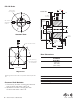
3. Position the assembly in accordance with
the overall axial dimensions given on the
illustration drawings. For air gap (.015'').
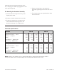
Electrical Specifications
Unit Size PB 120 PB 170
Voltage – DC 6 24 90 6 24 90
Resistance @ 20°C — Ohms 6.32 104 1386 6.96 111.2 1506
Current — Amperes .949 .230 .065 .861 .215 .060
Watts 5.69 5.52 5.85 5.85 5.16 5.37
Coil Build-up — Milliseconds 12 12 11 17 17 16
Coil Decay — Milliseconds 88 78 76
Unit Size PB 250 PB 400
Voltage – DC 6 24 90 6 24 90
Resistance @ 20°C — Ohms 5 76.4 1079 4.88 73 1087
Current — Amperes 1.2 .314 .084 1.23 .322 .083
Watts 7.2 7.5 7.51 7.39 7.96 7.45
Coil Build-up — Milliseconds 48 48 44 154 154 154
Coil Decay — Milliseconds 15 15 13 62 60 55
Notes: Build-up time equals current to approximately 90% of steady state value and flux to 90%.
Decay time equals current to approximately 10% of steady state value and flux to 10%.
4. Secure the assembly in this position by
alternately tightening the two setscrews in the
hub.
5. The hub will need to be repositioned as wear
occurs with time.