
Manual


7
Warner Electric • 800-825-9050 P-201 • 819-0485
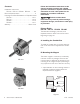
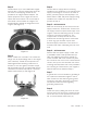
Step 2
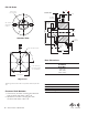
Fasten bracket (1) to clutch field/brake magnet
with one No. 10-32 hex washer head screw (2).
The screw is self-tapping, threads are not
provided in the magnet bracket adapter. The
square projection on the magnet fits into the
square hole in the bracket. The curved side of
the bracket mounts toward the magnet. The
bracket flange is toward the flange side of the
magnet. (See Figure 11)
Figure 11
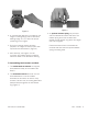
Step 3
Mount conduit box to bracket. The conduit box
flange must be toward flange side or the magnet
(rear of bracket). Thread terminal spacers into
field/magnet before fastening conduit box to
bracket. Do not over tighten, excessive torque
will pull thread insert out of magnet/field. Secure
conduit box to bracket with two No. 10-32 hex
washer head screws (4). (See Figure 12)
Figure 12
Step 4
Connect electric supply cable to the fitting
installed on the conduit box. If an external power
supply is furnishing DC current to the clutch or
brake, proceed to Step 5 and skip Step 6. If a
Warner Electric CBC-100 power supply is being
installed in the conduit box, skip Step 5 and
proceed to Step 6.
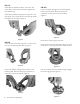
Step 5 - DC Connection
Slide one terminal cap (8) onto each of the two
supply conductors, small end first. Connect the
two supply conductors (with rubber caps) to the
magnet or field terminals using two No. 8 brass
screws (11) and ring terminals (9-1). The
stripped wires can wrap around the screw
between the terminal ring and the screw head
or other ring type terminals may be used.
Electrical supply connections must confirm to
local electrical codes. Install plug (12) into cover
hole.
Step 6 - AC Connection
When a CBC-100 power supply is used, refer
to installation sheet P-266 provided with the
CBC-100, following instructions carefully. To
mount the CBC-100 to the conduit box, place
the control into the cover so the curved surfaces
conform, line up the cover hole with the control
mounting hole and fasten with screw provided in
the mounting kit. Connections to the magnet or
field terminals are as outlined in Step 5.
Step 7
A ground wire is recommended for grounding of
the conduit box and brake magnet or clutch
field. Connect this wire with the green ground
screw (9) to the hole in the bottom of the box.
Consult electrical local codes regarding
grounding requirements.
Step 8
Install cover (10) by sliding the slot in the cover
over the tab on one end of the conduit box and
secure the cover on the opposite end with one
No. 10-32 hex washer head screw (11).