Electromagnetic Particle Clutches Models: PMC-10A3, PMC-20A3, and PMC-40A3 P-223-2 819-0369 Installation Instructions
Contents Introduction . . . . . . . . . . . . . . . . . . . . . . . . . . .2 Installation Instructions . . . . . . . . . . . . . . . . . .2 Electrical Data . . . . . . . . . . . . . . . . . . . . . . . . .4 Mechanical Data . . . . . . . . . . . . . . . . . . . . . . .4 Start Up . . . . . . . . . . . . . . . . . . . . . . . . . . . . . .4 Maintenance . . . . . . . . . . . . . . . . . . . . . . . . . .5 PMC-10 and 20 Dimensions . . . . . . . . . . . .5-6 PMC-40 Dimensions . . . . . . . . . . . . . . . . . . .
Pre-Mounting Mounting Note: Unit performance can be affected by prolonged exposure to humid environments. Please store in a dry location. Note: Do not use excessive force when mounting couplings, pulleys, or sprockets on shafts. Note: The equipment covered by this service manual must be installed in accordance with these instructions. Failure to do so may damage the equipment and void the warranty. Note: For proper function, mount magnetic particle units horizontally.
Electrical Connections Start Up To avoid injury (or even death), always make certain all power is off before attempting to install or service the control or any electrical equipment. The powder in the magnetic particle units sometimes settles during shipment and will need to be redistributed. A simple run-in procedure should be performed to ensure proper performance. The PMC-A3's operate on DC voltage.
Maintenance Heat Make sure your unit does not overheat. This occurs when the heat generated is greater than the heat dissipation capability of the unit. The maximum allowable surface temperature for the PMC-A3 series unit is 167° F. Slip Applications With most controls, torque is easily adjusted. However, care must be taken when adjusting torque to make sure that too much heat is not generated in the unit. The heat generated is proportional to torque and slip rpm.
Dimensions PMC – 10 & 20 Lead Wire Length = 300mm (11.
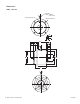
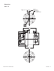
Dimensions PMC – 40 4-M4T 6 (0.24) on a 60 (2.36) B.C. Lead Wire Length = 300mm (11.8 inches) 4-ø 4.5 (0.18) on a 100 (3.94) B.C. 12.018 12.000 0.4731 0.4724 ( ) 97 (3.82) 10 (0.39) 6 (0.24) 86.000 85.965 3.3858 3.3844 ( 112 (4.41) ) 4 (0.16) 22 (0.87) 21 (0.83) 8.7 (0.34) 15 (0.59) 4 (0.16) 50 (1.97) 20 (0.79) 86 (3.39) 70.000 69.970 2.7559 2.7547 ( ) Hollow output shaft - both ends 59 (2.
Warranty Warner Electric LLC warrants that it will repair or replace (whichever it deems advisable) any product manufactured and sold by it which proves to be defective in material or workmanship within a period of one (1) year from the date of original purchase for consumer, commercial or industrial use. This warranty extends only to the original purchaser and is not transferable or assignable without Warner Electric LLC’s prior consent. Warranty service can be obtained in the U.S.A.