
Owner's manual


2
Warner Electric • 800-825-9050 819-0369
Contents
Introduction . . . . . . . . . . . . . . . . . . . . . . . . . . .2
Installation Instructions . . . . . . . . . . . . . . . . . .2
Electrical Data . . . . . . . . . . . . . . . . . . . . . . . . .4
Mechanical Data . . . . . . . . . . . . . . . . . . . . . . .4
Start Up . . . . . . . . . . . . . . . . . . . . . . . . . . . . . .4
Maintenance . . . . . . . . . . . . . . . . . . . . . . . . . .5
PMC-10 and 20 Dimensions . . . . . . . . . . . .5-6
PMC-40 Dimensions . . . . . . . . . . . . . . . . . . . .7
Warranty . . . . . . . . . . . . . . . . . . . . .Back Cover
Introduction
This service manual provides information
required for the installation, wiring, and mainte-
nance of Warner Electric's Magnetic Particle
Micro Clutch series. It also includes dimensions
and specifications. The three models covered in
this service manual are PMC-10A3, PMC-20A3,
and PMC-40A3. These models with their flanged
input hubs, also lend themselves to be mounted
as brakes. For selection information, please refer
to your Warner Electric Tension Control Systems
Catalog.
Warner Electric's Magnetic Particle clutches
provide smooth and controllable torque for a
variety of applications, including tension control,
cycling, and positioning. Quick response is
achieved by applying full rated voltage. Lower
voltage can be applied for softer engagements.
Extremely accurate tension control can be
achieved when these brakes are used with one
of Warner Electric's wide range of tension con-
trols for electric clutches.
Failure to follow these
instructions may result in product damage,
equipment damage, and serious or fatal
injury to personnel.
Installation Instructions
Introduction
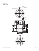
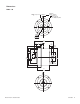
The design of the PMC-A3 series clutches
makes them easy to mount in various configura-
tions. They have a mounting flange on the out-
side diameter of the housing. The input is a
flanged hub, which is concentric to the double
ended output shaft. See Figure 1 for typical
mounting. To use the PMC-A3 as a brake, the
output shaft must be secured. See Figure 2.
Make sure all power is turned
off to this equipment when installing, as
injury (or even death) may result from contact
with live wires or rotating shafts.
Mounting bracket
Mounting bracket
Capscrews
Socket
head cap
screws
Set screws
Input hub
Timing pulley
Output shaft
Capscrews
Output shaft
Socket
head cap
screws
Input hub
Timing pulley
Output shaft
Capscrews
Flexible
coupling
Mounting
Bracket
Capscrews
Flexible
coupling
Output shaft
Figure 2* - Mounted as a brake
*Note: Shaded items are customer supplied
Figure 1* - Mounted as a clutch