
Owner's manual


3
Warner Electric • 800-825-9050 819-0369
Pre-Mounting
Note: Unit performance can be affected by
prolonged exposure to humid environments.
Please store in a dry location.
Note: The equipment covered by this service
manual must be installed in accordance with
these instructions. Failure to do so may dam-
age the equipment and void the warranty.
1. Remove the magnetic particle clutch from its
shipping carton and inspect it thoroughly to
ensure that it has arrived in good condition.
When handling, please take care not to dam-
age lead wires.
2. Check the input hub to make sure it turns
freely when the output shaft and housing are
held stationary. The powder inside the unit
may settle due to shock and vibration caused
during shipping. This can make rotation
noticeably difficult and can be easily reme-
died by turning the unit upside down and
gently tapping the outside to loosen the pow-
der.
3. Make sure the location chosen for mounting
will not expose the unit to water or oil. If
water or oil gets into the powder cavity, the
performance of the unit may be affected. If
the unit is mounted next to a gearbox, spe-
cial care should be taken to prevent oil from
working its way into the unit.
4. If couplings are used to make drive system
connections, the mounting surface must
properly locate the housing to ensure that
alignment is within the coupling manufactur-
er's specifications.
Mounting
Note: Do not use excessive force when mount-
ing couplings, pulleys, or sprockets on shafts.
Note: For proper function, mount magnetic
particle units horizontally.
For mounting dimensions, please refer to pages
5-7 of this service manual.
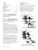
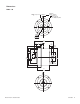
As A Clutch
Step 1: Bolt Unit in Place
Mount the unit to a vertical surface, using cus-
tomer supplied fasteners. See Figure 1.
Step 2: Make Mechanical Connections
Mount couplings, pulleys, or sprockets to the
male shafts per the manufacturer's recommen-
dations. The pulleys, sprockets, couplings,
mounting brackets, and bolts are customer sup-
plied. (The output shaft can be used as the input
and the input hub as the output, but the output
inertia will be higher.)
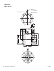
As A Brake
Step 1: Bolt Unit Into Place
Secure the mounting flange and the output shaft
as shown in Figure 2. Take care to insure that
alignment is true and there is no binding in the
bearings.
Step 2: Mount Pulley, Sprocket, or Coupling
Bolt the pulley, sprocket, or coupling to the
input hub of the unit. The pulleys, sprockets,
couplings, mounting brackets and bolts are cus-
tomer supplied.