
Owner's manual


5
Warner Electric • 800-825-9050 819-0369
Maintenance
Heat
Make sure your unit does not overheat. This
occurs when the heat generated is greater than
the heat dissipation capability of the unit. The
maximum allowable surface temperature for the
PMC-A3 series unit is 167° F.
Slip Applications
With most controls, torque is easily adjusted.
However, care must be taken when adjusting
torque to make sure that too much heat is not
generated in the unit. The heat generated is pro-
portional to torque and slip rpm. Refer to the
sizing procedure in the catalog to make sure the
unit has adequate heat dissipation capability.
Also, do not increase the slip speed or the
torque without verifying that the unit can dissi-
pate the heat.
Cycling Applications
In cycling applications, the speed and inertia of
the load and the cycle rate determines the heat
generated. Refer to the selection procedure in
the catalog to verify that the unit can handle the
thermal energy generated in your application.
Also, do not increase the speed, cycle rate, or
inertia without checking the units ability to dissi-
pate the heat generated.
Contamination
Do not expose the unit to water or oil. If water
or oil gets into the powder cavity, the perform-
ance of the unit may be affected. If the unit is
mounted next to a gearbox, special care must
be taken to prevent oil from working its way into
the unit.
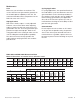
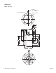
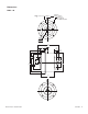
PMC-10A3 and PMC-20A3 Dimensional Data
Note: All dimensions are nominal unless otherwise noted.
Model A B C D E F G H I J K L M N
mm mm mm mm mm mm mm mm mm mm mm mm mm mm
(in.) (in.) (in.) (in.) ((in.) (in.) (in.) (in.) (in.) (in.) (in.) (in.) (in.) (in.)
PMC-10A3 58 77 14 4 15 12 12 8 6 10 10 51 76 30
(2.28) (3.03) (0.55) (0.16) (0.59) (0.47) (0.47) (0.31) (0.24) (0.39) (0.39) (2.01) (2.99) (1.18)
PMC-20A3 69 116 33 4 22 25 24 15 6 20 20 51 92 35
(2.72) (4.57) (1.30) (0.16) (0.87) (0.98) (0.94) (0.59) (0.24) (0.79) (0.79) (2.01) (3.62) (1.38)
Shaft Dimensions U V
PQRST
Thread Thread Bolt Hole Bolt
Size Depth Circle Size Circle
mm (in.) mm (in.) mm (in.) mm mm mm mm mm mm
(in.) (in.) (in.) (in.) (in.) (in.)
54.000
2.1260 58.000 2.2835 7.000 0.2756 6—M46464.5 68
53.970 2.1248 57.970 2.2823 6.985 0.2750 0.24 — (0.24) (1.81) (0.18) (2.68)
54.000
2.1260 69.000 2.7165 12.000 0.4724 11.5 11.5 M4 6 46 4.5 82
53.970 2.1248 68.970 2.7154 11.988 0.4720 (0.45) (0.45) (0.24) (1.81) (0.18) (3.23)