
Installation User Manual


2
Warner Electric • 800-825-9050 P-1423 • 819-0388
Positive
Clutch Switch
Clutch
Negative
Figure 1
Failure to follow these
instructions may result in product damage,
equipment damage, and serious or fatal
injury to personnel.
General
This pump clutch has been developed specifically
for use in pump applications. Properly installed, it
will provide maintenance-free service. The clutch
uses a stationary field that does not require slip
rings or brushes.
The clutch consists of two major components;
a stationary magnetic field assembly and a
rotor-pulley assembly. The field assembly is
mounted on the pump face. The rotor-pulley is
mounted to the pump shaft and driven by v-belts.
Electricity energizes the clutch field to couple the
clutch magnetically, thus driving the pump
mechanism. De-energizing the field releases
the clutch and uncouples the pump.
Wiring
The coil in the field assembly has a single leadwire
(hot) and is grounded through the field shell. It will
only be necessary to connect this leadwire to the
electrical system as the pump should already be
negatively grounded. Figure 1 shows an example
of a typical system.
Service
The clutch automatically compensates for wear
requiring no adjustments throughout the life of the
clutch. Do not lubricate the unit. If the clutch
should fail to operate, check the electrical circuit to
be sure the proper voltage is being supplied to the
clutch. Do not attempt to make any mechanical
adjustments to the clutch.
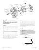
Cap Screw (5)
Washer (4)
Rotor-Pulley
Assembly (3)
Capscrews &
Lockwashers (2)
Field Assembly (1)
Rotor-Pulley
Assembly
Field
Assembly
Pump
(Not Included)