
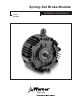
Owner manual
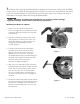

6. Secure the brake module to the motor
C-face with the four hex head capscrews and
washers that are provided. (Figure 3)
7. Rotate the brake housing to align the four
mounting holes with the threaded holes in the
motor face. If possible, position the brake
module with the ventilation slots
facing down to prevent foreign matter
from falling into the unit during operation.
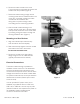
8. With the brake module housing in full
contact with the motor face, securely tighten
both input hub setscrews to the motor shaft
by inserting a long hex wrench through the
housing ventilation slots. (Figure 4)
Mounting to a Gear Reducer
1. Align the module output shaft and key
with the reducer bore and keyway.
2. Slide the assembly together until the module
and reducer faces are in full contact.
Do not use excessive force.
3. Secure the module to the gear reducer
flange using four 3/8-16, UNC-2A bolts
(typically furnished with the reducer).
Electrical Connections
The brake module housing is threaded for
standard conduit connectors. The brake lead
wires are fed through this hole and are to be
connected to a DC power source with the same
voltage as that listed on the brake module label.
An optional conduit box kit can be purchased to
facilitate this connection (Warner part number
5370-101-042).
If a user provided DC power source is not
available, any of Warner Electric’s CBC-100,
CBC-150, or CBC-801 controls may be used
(selection based on user requirements). Refer to
the installation sheet included with the
control for connection information.
Figure 3
Figure 4
3
Warner Electric • 800-825-9050 P-1249 • 819-0390