OFFICIAL WARWICK AMP OWNER MANUAL ENGLISH
Congratulations on the purchase of the new Warwick amplifier head/combo. Please read these instructions through before connecting and operating the device. If you keep to the guidelines set out in this manual, you will soon be able to appreciate the quality of this new Warwick amplifier. Please keep this instruction booklet handy in case you need to consult it again. Please send the PASSPORT to the address indicated therein.
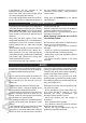
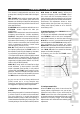
1. INPUT socket to plug in a bass guitar. 2. GAIN control + 3 LEDs to adjust the input level: CLIP too high, OK optimum, LOW too low. 3. CH. SELECT + 2-colored LED to switch from channel 1 (red) to channel 2 (green). 4. LIMITER switch + 2-colored LED to compress the signal (channel 2 only): green Limiter on, red the signal level is actually bein reduced. 5. For features of CHANNEL 1, please refer to the chapter CHANNEL 1-TUBE. 6. For features of CHANNEL 2, please refer to the chapter CHANNEL 2-SOLID STATE.
watts power amplifier provides respectively one XLR and one Speakon socket in parallel. The signal from the Speakon outputs is leaded by 1+ and 1-. LINE OUT PARALLEL TO SPEAKER OUT sockets allow to connect additional power amplifiers. BIAMP/FULLRANGE switches over between two operation modes of the power amplifier. In FULLRANGE mode the whole frequency range is provided by both SPEAKER OUT sockets. In BIAMP mode the signal is splitted by an active crossover.
CHANNEL 1 - TUBE As you can see, the three 3-way switches and TONE control act in a very complex way. Therefore I would like to introduce some remarks and suggestions regarding sound adjustments: 1. Simulation of different pickup characteristics: Each pickup has a peak in its resonance frequency in excess of which no treble can be transmitted. The main distinction in sound characteristics between different pickups is that this frequency is located elsewhere depending on pickup types.
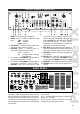
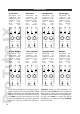
EXAMPLES Clean Funk Hard Funk Straight Rock Fat and ugly 2ND STAGE OFF CONTOUR ON TONE S. PICTURE CRUNCH S. PICT. LOW FLAT MID BOOST HIGH FLAT 2ND STAGE ON CONTOUR ON TONE S. PICTURE CRUNCH S. PICT. LOW BOOST MID CUT HIGH BOOST 2ND STAGE ON CONTOUR OFF TONE S. PICTURE CRUNCH S. PICT. LOW BOOST MID FLAT HIGH FLAT 2ND STAGE ON CONTOUR ON TONE S. PICTURE CRUNCH S. PICT.
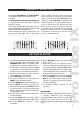
CHANNEL 2 - SOLID STATE section might illuminate, which means you enter the overload range before the master control. In this case reduce OUTPUT from channel 2. If the LIMITER is activated and threshold appears too high, readjust the EQ curve to lower levels (2). Reducing GAIN would result in a worse S/N ratio and can eventually not be recommended. Should you find the threshold is too low, i.e. more intense compression is desired, shift the EQ curve further to the positive area. 1 2 LOW BOOST 2 +12 .
Pro Tube IX NOTES 28
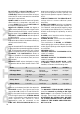
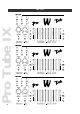
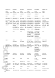
Sonic II / III Pro Fet III Pro Fet IV Pro Tube IV Pro Tube IX Quad IV / VI 25 mV 25 mV 25 mV 25 mV 25 mV 25 mV transistor, controlled active active transistor, controlled active transistor, controlled active transistor, controlled active all tube dual tube none fan cooled (non fan cooled (non permanent) permanent) fan cooled (non permanent) fan cooled (temperature controlled) 3-way switches for low boost/flat/cut mid boost/flat/cut high boost/flat/cut param.freq.contr.
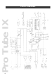
Pro Tube IX CIRCUIT DIAGRAM 42
Headquarters: Warwick GmbH&Co.Music Equipment KG•Gewerbegebiet Wohlhausen•08258 Markneukirchen/Germany•Tel 0049-(0)37422-555-0 Fax 0049-(0)37422-555-99 • Send us an E-Mail to: info@warwick.de • Visit us on the World Wide Web: http://www.warwick.de Branch China: Warwick Music Equipment (Shanghai) Ltd., Co.Shanghai Waigaoqiao Free Trade Zone • Shanghai 200131 / P.R.