OPERATING & MAINTENANCE MANUAL FL 125 HI-TEK FL 185 HI-TEK 471 1562-56/01 95.32 WARNING: ALL OPERATING AND MAINTENANCE PROCEDURES SHOWN ON THE NEXT PAGE OF THIS MANUAL MUST BE FOLLOWED DAILY FOR PROPER OPERATION OF YOUR WASCOMAT MACHINE. PLEASE ENTER THE FOLLOWING INFORMATION AS IT APPEARS ON THE MACHINE(S) DATA PLATE(S). MACHINE TYPE OR MODEL MACHINE SERIAL NUMBER(S) ELECTRICAL CHARACTERISTICS: ________ VOLTS, _______ PHASE, ______ HZ.
II NOTICE TO: OWNERS, OPERATORS AND DEALERS OF WASCOMAT MACHINES IMPROPER INSTALLATION AND INADEQUATE MAINTENANCE, POOR HOUSEKEEPING AND WILLFUL NEGLECT OR BYPASSING OF SAFETY DEVICES MAY RESULT IN SERIOUS ACCIDENTS OR INJURY. TO ASSURE THE SAFETY OF CUSTOMERS AND/OR OPERATORS OF YOUR MACHINE, THE FOLLOWING MAINTENANCE CHECKS MUST BE PERFORMED ON A DAILY BASIS. 1.
SAFETY AND WARNINGS SIGNS Replace If Missing Or Illegible One or more of these signs must be affixed on each machine as indicated, when not included as part of the front instruction panel. LOCATED ON THE OPERATING INSTRUCTION SIGN OF THE MACHINE: CAUTION PRECAUCION 1. Do not open washer door until cycle is completed, operating light is off, and wash cylinder has stopped rotating. 1.
FLEX-O-MATIC FL 125, FL 185 HI-TEK Contents Introduction ...................................................................... 1 Technical data .................................................................. 2 Installation ........................................................................ 5 Safety rules .................................................................... 15 Mechanical and electrical design ................................... 16 Procedure for use ..................................
Introduction 1 Introduction The FL HI-TEK model washer/extractors have been developed to cover the heavy duty requirements of hotels, motels, nursing homes, hospitals, professional laundries, restaurants, airlines, ships, schools, colleges and all on-premises laundries where flexibility and quick formula variation coupled with high quality automatic washing are required. Fig.
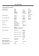
2 Technical data Technical data FL 125 HI-TEK Dry load capacity up to Overall dimensions Width Depth Height Net weight Dyn force 775 mm 995 mm 1196 mm 210 kg 2.4 ± 4.8 kN 30 1/2 in 39 3/16 in 47 3/32 in 462 lbs 576 ± 1152 lbs force Crated dimensions Volume Weight 1,06 m3 222 kg 39 cu.ft 489 lbs Inner drum dimensions Diameter Depth Volume 620 mm 520 mm 157 litre 24 1/2 in 20 1/2 in 5.65 cu.ft Speed of rotation Wash Extraction 52 r.p.m. 500 r.p.m. G-factor During wash During extraction 0.
Technical data 3 Technical data FL 185 HI-TEK Dry load capacity up to 23 kg 50 lbs Overall dimensions Width Depth Height Net weight Dyn force 860 mm 1085 mm 1315 mm 264kg 3.1 ± 5.2 kN 33 7/8 in 42 3/4 ın 51 3/4 in 582 lbs 744 ± 1248 lbs force Crated dimensions Volume Weight 1,42 m3 275 kg 50.2 cu.ft. 606 lbs Inner drum Diameter Depth Volume 700 mm 600 mm 230 litre 27 9/16 in 23 5/8 in 8.1 cu.ft Speed of rotation Wash 45 r.p.m. Extraction 455 r.p.m.
4 Technical data Outline and dimensions FL 125HI-TEK mm inches mm 1196 47 1/16 1315 51 3/4 B 465 C 775 D 995 E 205 F 160 G 1040 H 1035 J 100 K 270 L M N 1135 18 5/16 30 1/2 39 3/16 8 1/16 6 5/16 40 15/16 40 3/4 3 15/16 10 5/8 44 11/16 540 860 1085 205 160 1160 1155 100 260 295 1215 1255 21 1/4 33 7/8 42 11/16 8 1/16 6 5/16 45 11/16 45 1/2 3 15/16 10 3/8 11 5/8 47 13/16 49 7/16 A 1 Drain outlet 1 1 FL 185 FL 125 1852 FL 185HI-TEK inches
Installation Installation 5 2 Machine foundation Fig. 2 Fig. 3 Fig. 4 The machines are designed to be bolted in position to a concrete floor or specially prepared concrete foundation. A template showing the size of the foundation and positioning of the foundation bolts is delivered with each machine. For installation on an existing concrete floor, the floor must be at least 8" thick and of good quality.
Installation 6 Mechanical installation Fig. 5 5 • Place wide steel shims on the concrete foundation over the bolts. • Lift the machine and lower it in position. Never use the door or the door handle to lift or lower the machine. Fig. 6 Fig. 7 • Check that the machine is level front-to-rear and side-to-side and standing firmly on the six supporting points. Spacing washers must be mounted if one or more of these points is not resting against the floor/foundation.
Installation Electrical installation 7 8 All electrical installations are to be carried out by licensed personal. Fig. 8 Although the machines are fitted with a thermal overload in the motor windings and a separate fuse for the control circuit, a separate threephase common-trip circuit breaker must be installed for all three-phase machines. For proper overcurrent protection, check the data plate at the rear of the machine. Also consult local electrical code for special requirements. Fig.
Installation 8 Water connection 11 NOTE All plumbing must conform to national and local plumbing codes. Fig. 11 Incoming water lines do not require non-return or back-suction valves, as the machine is already fitted with a siphon breaker. However, all incoming lines must be fitted with shut-off valves. • Use flexible water hoses of proper length to avoid sags and kinks. Fig. 12 • Water inlets are labelled for hot and cold water connection.
Installation Steam connections (optional) 9 14 The steam supply to the machine should be fitted with manual shut-off valves and filters to facilitate installation and servicing. Fig. 14 Fit the filter supplied to the manual cut-off valve. Connection size at filter: DN 15 (BSP 1/2''). Steam pressure required: • minimum: 10 psi (0.5 kp/cm2) • maximum: 115 psi (8 kp/cm2) Check there are no sharp angles or bends in the connection hose. Fig.
Installation 10 Drain connection Fig. 16 16 Connect a 3" (75 mm) flexible hose to the drain outlet of the machine. The drain hose must not have sharp bends and must slope from the machine to assure proper drainage. The outlet must open freely to the main drains. Do not reduce the size of the drain connection from the machine to the waste line. Start-up and safety checklist Before initial start-up of a Wascomat washerextractor, the following safety checks must be performed: Fig. 17 Fig.
Installation Connection of external liquid supply 11 19 Remove cover and cover support over the soap box. Fig. 19 Fig. 20 Fig. 21 Bend all the way back the metal plate in compartment 3. Pull the knobs up and forward. 1. Loosen both knobs so that one side of the metal fingers underneath can slide under the top lid of the machine, within the supply box. 2. Fit the supply injector into the supply box so that both sides are held securely in places by the metal fingers.
Installation 12 Fig. 22 1. Drop the knop into the larger opening in the supply injector lid. 22 2. Tighten securely. Do not overtighten! Do not use pliers or other tools to tighten the knobs! Fig. 23 1. Stretch the multi-rubber ring B and select the correct size ring which will fit snugly on the chemical tube you are using. Ring A is used for tubes with Ø1/3'' (8 mm). 2. Use scissors or a razor to carefully cut out the proper size rubber ring.
Installation Electrical connection Fig. 24 13 24 At the electrical connection of the machine are two quick connectors. When the machine is delivered connector A is connected. When using powder supply, change to connector B. Pump connection Fig. 25 To the right of the incoming power connection block is the connection strip for pumps. Depending on the number of pumps to be connected, they shall be connected from 1-5 and C (common) on resp. connection.
Installation 14 Before the machine is operated, the door safety interlock must be checked for proper operation as follows: Fig. 26 Fig. 27 26 • When washer loading door is open, the machine must not start. Verify this by attempting to start washer with door open (see section ”Procedure”). • When washer is in operation, the loading door is locked and cannot be opened. Verify this by attempting to open the loading door when the machine is operating.
Safety rules Safety rules • All installation operations are to be carried out by qualified personnel. Licensed personnel are necessary for all electric power wiring. • This machine is designed for water washing only. • This machine must not be used by children. • This machine must not be sprayed with water, otherwise short circuiting may occur. • Fabric softeners with volatile or inflammable fluids are not to be used in the machine.
Mechanical and electrical design 16 General The door and the electronic timer with display and keyboard are fitted at the front of the machine. All control and indicating components, i.e. relays, level control, etc are assembled under the top cover, easily accessible from the top of the machine for simplified servicing. Main units Fig. 29 1. Electronic timer with display and keyboard for operating the machine. 2.
Mechanical and electrical design 17 Machine construction Outer shell Fig. 29 The outer shell is made of heavy gauge surgical steel and is attached to a heavy duty, rigid head casting (back gable). The whole assembly is mounted on a heavy gauge fabricated steel base, galvanized for long life and corrosion resistance. Inner cylinder The inner cylinder is made of perforated surgical stainless steel.
Mechanical and electrical design 18 Rear gable and bearing Fig. 30 The rear gable and the bearing trunnion housing are constructed of a webbed heavy casting for extra rigidity. There are two neoprene seals to protect from filtration of water. The sleeve bearings are water protected. An intermediate safety outlet provides an escapement for any possible condensation.
Mechanical and electrical design Door, description Fig. 31 The door consists of a backing frame (1), door (2), glass (3) and door gasket (4). The backing frame and door are both made of enameled aluminium. The backing frame is bolted directly to the outer shell of the washing machine.The door hinges are fastened on the outside of the backing frame and the door lock (5) on the inside.
Mechanical and electrical design 20 Control unit Fig. 33 The control panel (1), mounted at the front, includes all components necessary for operating and programming the machine. The panel includes display, control switches and a key-operated switch. The printed circuit board with the microprocessor-controlled electronic timer is mounted just behind the control panel. Relays, rotation guard, capacitors (1-phase only) and transformer are located at the top of the machine, easily accessible for service.
Mechanical and electrical design Relays Fig. 34 21 34 The HI-TEK models employ three relays. The relays control: • the wash speed (1) • the extract speed (2) Construction Fig. 35 The body of the relay holding the stationary contacts is made of current-resistant plastic. A solenoid and a contact bank hold the moving contacts. The contacts are spring-loaded to assure the correct contact pressure. The relay is constructed for continous operation, whether mounted horizontally or vertically.
Mechanical and electrical design 22 Drive motor 36 Description in general Fig. 36 Fig. 37 The motor is mounted on an axle with rubber dampeners. The V-belt is tightened by turning the motor on the axle and locking it in place using the tensioner on the rear side of the motor. The motor and tensioner have vibration and noise dampening rubber suspensions. Construction in general The motor consists of stator, rotor and endshields with ball-bearings.
Mechanical and electrical design 23 Principal wiring and points of measuring on single-phase motors. Fig. 38 The numbers at the connection points refer to the terminal numbers at the motor connector plug. The numbers in circles indicate points of ampere measurements.
Mechanical and electrical design 24 38 FL185 HI-TEK 208-240 V 60 Hz single-phase 1791
Mechanical and electrical design Motor connections Fig. 1, 2 and 3: wash speed (18-pole winding). 39 4, 5 and 6: extract speed (2-pole winding) 25 39 7 and 9: motor overload protector. Motor overload protector Blue White Black The motor is equipped with two self-resetting, thermal overload protectors, situated one in each winding of the stator. The protectors are connected in series and will trip at a temperature of 120°C (248°F) (3-phase) or 130°C (266°F) (single phase).
Mechanical and electrical design 26 Inlet valves for FL 125 HI-TEK and detergent valve for FL 185 HI-TEK 41 Construction Fig. 41 The valve has a single-inlet with either one, two or three outlets, each with its own solenoid coil. The body is made of heat-resistant polyamid plastic and the solenoids encased in water-tight plastic. A filter screen on the inlet side prevents dirt from entering the valve. Flow restrictors can be placed at either the inlet or any of the outlets. Operation Fig.
Mechanical and electrical design Repair instructions Fig. 43 27 43 Limescale can block the hole in the valve diaphragm and interfere with the function of the valve. It is therefore advisable to dismantle and clean the valve at certain regular intervals. The frequency depends on operating conditions and the level of contamination in the water. If the valve does not open • Check that power is supplied to the coil.
Mechanical and electrical design 28 Inlet valve for FL185 HI-TEK Fig. 46 46 The water inlets have brass bodies with larger cross section of the outlet in order to achieve a shorter filling time for the machine. Construction The valve housing is made of pressed brass. The spring-loaded plunger is made of stainless steel and located at its lower end is a rubber gasket for the pilot valve.
Mechanical and electrical design 29 Soap supply box Fig. 49 The three-compartment soap supply box is located at the top of the machine. Viewed from the front, the compartments marked with figures 1, 2 and 3 are used as follows: For powder supplies: Compartment 1 This compartment is used for adding detergent to the wash and is flushed down when Comp. 1 is programmed. Compartment 2 This compartment is used for adding supplies to the wash and is flushed down when Comp. 2 is programmed.
Mechanical and electrical design 30 Drain valve 50 Description Fig. 50 The drain valve is operated by using the pressure in the cold water intake. A tube (1) is connected between the cold water intake and a solenoid valve (2). When the solenoid valve is activated, it opens and allows water to flow into the feeder tube (3). The water presses up a piston (4), which uses the pressure lid (5) to close the drain valve rubber membrane.
Procedure 31 Procedure for use All operations, including the programming of new wash programs are carried out from the control panel on the front of the machine. During normal use, the programming keys to the left of the panel are inoperative. Fig. 51 The control panel comprises the following: • a display window with four lines each of 40 characters. This shows the relevant program information, the programming instructions, error messages etc.
Procedure 32 Preparation 52 • Sort the wash according to the washing instructions on the garment labels. Check that there are no foreign objects in the garments. Pull up zipper fasteners. • Open the washing machine door, check that the drum is empty, insert the wash goods and close the door. Automatic washing The manual controls can be used during automatic washing. Program selection When supplied, the machine is provided with a number of standard programs (program numbers 01-09).
Procedure Program information Fig. 54 33 54 When a program has been selected and PROG. INFO. is pressed, further information about the program is shown in the display window's bottom lines. Measuring the detergent Fig. 55 Fig. 56 Five lights on the panel indicate which detergent compartments will be used, or supply signals provided during washing. Will be lit when specific detergent compartment is used, or signal provided. HOT WATER DRAIN CLOSED MOTOR FLUSH PROG. INFO.
Procedure 34 Starting the program Fig. 57 Fig. 58 57 Press START/HOLD/RAPID ADV. button. The wash cycle will commence and the display window will display wash information as shown in the figure below. Temporary stop Fig. 57 Fig. 57 • Press START/HOLD/RAPID ADV.. All active functions (motor, filling with water and heating) are switched off. The drain will remain closed and the door locked. START HOLD/RAPID ADV. HEAT LOW EXTR.
Procedure Programmed stop Fig. 59 If there is a programmed stop in the program, the machine stops and a buzzer sounds. The buzzer is switched off by pressing START/ HOLD/RAPID ADV. The program is restarted by pressing the button again. 35 59 Tumble drying after the program is completed Fig. 60 If DOOR LOCK and MOTOR are pressed before starting or while a program is operating, the drum will continue to rotate after the program is completed. The drum is stopped again by pressing MOTOR again.
Procedure 36 Manual washing 61 • The lamps above the control buttons indicate that the function is active. COLD WATER, HOT WATER and FLUSH must be kept pressed to remain active. Other control buttons change function each time they are pressed. Fig. 61 Fig. 62 Fig. 63 Fig. 64 Fig. 65 DRAIN CLOSED FLUSH MOTOR PROG. INFO. DOOR LOCK °C/°F • Lock the door by pressing DOOR LOCK (the lamp above the shall light up). Note that the door must be locked for other manual operation to be possible.
Procedure Extract cycle 37 66 For safety reasons, there is no manual button for the extract cycle. There are two choices if extracting is required during manual operation: • 1. Select one of the standard programs and fast forward to the "Extract" cycle. DRAIN MOTOR CLOSED FLUSH PROG. INFO. DOOR LOCK °C/°F • 2. Program your own program by draining and extracting for the required time.
Programming 38 General Fig. 70 The washing machine’s program operation is controlled by a microcomputer and the wash programs are stored in an electronic memory. Program controls are very exact and the wash programs can be easily adapted to the end user’s individual requirements. The machine is supplied with a number of fixed basic programs which cannot be deleted or modified. However, they can be used as a background for programming end user programs.
Programming Programming - general description Programming can be divided into two programming principles: Programming a new program or using an old program as a background. 39 71 Turn the key to ''PROGRAM'' Programming a completely new program Fig. 71 The wash program is constructed by selecting different sub-programs with the buttons on the panel. These sub-programs, when stored after each other, form the complete final wash program. Sub-programs can be selected in an optional sequence.
40 Programming Using an old program as a background Fig. 72 In this operation, an old program is selected as a background for the new one. The answers to the questions and the written texts can be changed to create a new program. Furthermore, subprograms can be erased and new sub-programs entered in optional positions. When the changes are complete, the new program is entered under a vacant program number.
Programming Controls 41 73 The key switch Fig. 73 Turn the switch to the PROGRAM position if the wash program is to be programmed or changed. If for any reason you wish to discontinue programming and start again, turn the switch to the RUN position and then back to PROGRAM again. Any programming that you have done so far will be deleted but other programs already stored will not be affected. RUN PROGRAM ENTER Fig.
Programming 42 Erase Fig. 76 76 This button can be used in three different ways: PROGR. MODE SELECT SEQUENCE PREWASH 01 • Deleting a complete program. Press ERASE when the display window displays the adjacent text. A warning text will then be displayed. Press ENTER, enter the program number with the number keys and press ENTER again. Fig. 77 78 RA- ERASE DERA Number keys ENTER KLAR ENTER KLAR • Deleting a section of a program.
Programming YES, NO, number keys Fig. 80 These keys are used to answer the different questions which are found under each subprogram. All answers must be followed by pressing ENTER for the answer to be registered. 43 80 PRE MAIN WASH WASH DRAIN EXTR. TEXT EDIT TEXT Fig. 81 The key for TEXT is used for entering the explanatory text which is displayed when PROG.INFO. is pressed after that a program is selected.
Programming 44 Programming a new program 84 If you make a mistake or get stuck, there is always a final resort: RUN Turn the key to the RUN position and then to PROGRAM again. Any programming you have carried out so far will be lost but other programs will not be affected. PROGRAM Turn the key Fig. 84 Turn the key to the PROGRAM position. The first character will then be displayed in the display window. 0167 85 PROGRAMMING MODE: DO YOU WANT AN OLD PROG.
Programming Answering questions The general principle for answering questions is the same for all sub-programs: • The cursor (the flashing square) is always to the right of line three in the display window. This means that it is the question on line three that is to be answered. Fig. 87 88 Fig. 89 Fig. 90 87 PROGR.
Programming 46 The following is a summary of the different questions that can appear under the different buttons. 91 PROGR.MODE SELECT SEQUENCE PREWASH PAUS WITH BUZZER Y/N NORMAL ACTION DURING FILLING Y/N 01 N N NOTE: The question which are described do no apply to all machines. On certain types of machines, some of the values are programmed as standard values and need therefore not be answered. Press: YES JA KLAR ENTER or RED. EDIT RED.
Programming Refilling Fig. 95 LEVEL RESET is the value which regulates at which level water is to be refilled if the water level drops while a wash is in progress. 47 95 PROGR. MODE SELECT SEQUENCE LEVEL 000 UNITS LEVEL RESET 000 UNITS TEMPERATURE 000 °C PREWASH 01 Example: The following values are programmed: Press: • Level: 130 units Number keys • Level reset: 10 units KLAR ENTER or EDIT RED. JA DOWN NED This means that: • Water is filled to level 130 at the beginning of the sub-program.
Programming 48 Water filling FIg. 98 98 One or several water valves can be selected. If you decide to use hot and cold water, both valves will be open while filling is in progress. The hot water valve will be automatically closed if the pre-set temperature is exceeded. The valve will open again if the temperature drops below the preset value. PROGR.MODE SELECT SEQUENCE PREWASH WASHTIME 00 MIN. 00 SEC. COLD WATER Y/N HOT WATER Y/N Fig. 99 Fig. 100 • 1.
Programming Drain Pause with signal Fig. 101 If the question is answered with YES, the washing machine will stop before the sub-program starts and a buzzer will sound. 49 101 PROGR.MODE SELECT SEQUENCE DRAIN PAUSE WITH BUZZER Y/N NORMAL ACTION Y/N 102 Drain 1/Drain 2 Fig. 103 JA YES Select the method of working while draining. Distribution action is used before a spin cycle so that garments are equally distributed around the drum. NO to all three questions will cause the drum to be stationary.
Programming 50 Programming complete • When ’’END OF SEQUENCE’’ appears on the third line of the display window and all questions are answered, press EDIT DOWN. 105 PROGR.MODE SELECT SEQUENCE EXTRACT TIME HIGH SPEED TIME LOW SPEED • Answer NO to the question ’’END PROG. SESSION Y/N?’’ if there are more subprograms to be answered. Answer YES if the sub-program is the last in the completed program. The continue under the heading ’’Looking through the program’’. 00 MIN. 00 MIN. 00 SEC. 00 SEC.
Programming Special cooling valve FIg. 107 Answer YES is there is a separate water valve used for cooling. If the answer is NO, the standard cold water inlet is used. 51 107 PROGR.MODE SELECT SEQUENCE COOL DOWN PAUSE WITH BUZZER Y/N SEPARATE COOL DOWN VALVE Y/N GENTLE ACTION Y/N 01 N N N Gentle action Fig. 108 Press: Answer YES if the machine is to operate on gentle action during cooling. The machine will operate on normal action if the answer is NO. JA YES KLAR ENTER or RED. EDIT RED.
52 Programming Example: 111 • ON TIME 212-158°F (100-70°C) 8 seconds. • ON TIME 158°F (70°C) - END 13 seconds. • END TEMP. 113°F (45°C). • Wash temperature 194°F (90°C). The following takes place: Fig. 111 • When the water in the drum reaches 194-158°F (90-70°C), the water valve is ON 8 seconds, OFF 22 seconds, ON 8 seconds, OFF 22 seconds etc. providing the temperature in the drum does not decrease by more than 7°F (4°C)/minute.
Programming Text 53 114 Each program can be provided with two types of informative text: Fig. 114 Fig. 115 • 1. A program name which is always displayed when the program is selected when washing. This text is programmed when the program number i selected. See under the heading ’’Program names’’ later on in the manual. SELECT PROGRAM TOW DIGITS PROGRAM 01 HEAVY SOIL START WASH WITH START-BUTTON FOR PROGRAM INFO. PRESS PROG.INFO • 2.
Programming 54 Times for normal action and gentle action Fig. 118 Fig. 119 The times for rotating and stationary drum during normal and gentle action can be programmed. All times can be selected within the range of 0-30 seconds with 1 second intervals. 118 PROGR.MODE MAINDATA BUZZER ON WHEN PROGRAM FINISHED Y/N GENTLE ACTION ON TIME 00 SEC. GENTLE ACTION OFF TIME 000 SEC. Press ENTER when ’’TO END. PRESS ENTER’’ is displayed in the display window. Press: Number keys Entering the program number Fig.
Programming Program names Fig. 122 You can now give the program a name which will be displayed when the program is selected during washing. The text can be up to 29 characters long. 55 122 -ABCDEFGHIJKLMNOPQRSTUVWXYZ !&/()=?;:,.* PROGRAM 10 - The way in which text is entered described under the heading ’’TEXT’’ earlier in the manual. Press: Saving programs Fig. 123 Fig. 124 Fig. 125 EDIT UP When the program has been given a name, the program is saved in the program memory.
Programming 56 Starting from a previously saved program 126 If you make a mistake or get stuck, there is always a final resort: RUN Turn the key to the RUN position and then to PROGRAM again. Any programming you may have carried out so far will be lost but other programs will not be affected. PROGRAM 0167 Turn the key Fig. 126 Turn the key to the PROGRAM position. The first question will now be displayed in the display window. 127 PROGRAMMING MODE DO YOU WANT AN OLD PROG.
Programming Fig. 130 Fig. 131 The cursor will appear on the first line of this subprogram. Use EDIT UP and EDIT DOWN to move within the sub-program to reach the line(s) to be altered. 57 130 PROGR.MODE SELECT SEQUENCE MAINWASH 01 PAUSE WITH BUZZER Y/N NORMAL ACTION DURING FILLING Y/N NOTE Press: ENTER is to be used only as an acknowledgement when sub-questions are to be altered. Use buttons EDIT UP and EDIT DOWN to move around within the program. EDIT DOWN NO ENTER 0225 Fig. 132 Fig.
Programming 58 NOTE Use only EDIT UP and EDIT DOWN for looking through the program. ENTER shall only be used for making changes in the program. 134 PROGR. MODE SELECT SEQUENCE PREWASH PAUS WITH BUZZER Y/N NORMAL ACTION DURING FILLING Y/N GENTLE ACTION DURING FILLING Y/N 01 Y Y N Press: Making changes to the program FIg. 134 EDIT DOWN EDIT UP Use EDIT UP and EDIT DOWN so that the question to be changed is on the third line in the display window.
Programming Altering text The text that is displayed when a program is selected and PROG.INFO is pressed can be altered. Fig. 138 Fig. 139 59 138 PROGR.MODE SELECT SEQUENCE Go to the position between two sub-programs (see the section ’’Looking through the program’’). Press TEXT and ENTER. Any text that might have been programmed in the old program is displayed. Press: TEXT TEXT Refer to heading ’’TEXT’’ earlier in the manual when entering text. 0233 139 -ABCDEFGHIJKLMNOPQRSTUVWXYZ !&/()=?;:,.
Service information 60 Service information Fig. 142 The machine's electrical power connection cable shall be provided with a safety ground to avoid breakdowns in the machine's electronic program controls. If interference problems do occur, check first that the machine is properly grounded. The machine's operation in terms of safety and function is continuously monitored by the program unit.