
Service manual


78
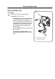
Door and door lock
6659
7
6
14
K21
M1
9
1
10
11
12
13
2
E1 – E3
8
2
3
4
5
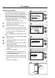
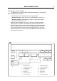
Function
The door lock locks the door
When the door is closed (closed door lock switch S3), the programme unit
may request door locking by applying a voltage of 200-240 V on the door
lock controller A31 input X92.
The following check is made by the A31 card prior to locking of the door:
• No water in drum - input "level" from level guard B2 is closed = 0 V
• Drum not turning - pulse frequency on input "Tacho" from rotation
sensor B3 less than 0.4 Hz.
When the above conditions are met, the card A1 outputs a closing pulse
on output D0 to the door lock actuator/coil, which then locks the door. The
micro switches S4a and S4b in the actuator/door lock are closed when the
door is locked. These micro switches feed voltage to:
• The output relays on the programme unit card. The relays control the
machine’sdrainandwatervalvesaswellasheaterswitch-on.
• Interlock signal for motor control (input X302) that releases the motor
start prevention state.
Programme operation is now possible.
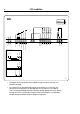
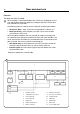
2
1. Program unit A1
2. Temperature sensor B1
3, Level switch B2
4, Level switch B4
5. Display A2
6. Heater element E1 -3
7. Motor control U1
8. Rotation sensor B3
9. Door lock module A41
10. Voltage unit A5
11. I/O board
12. Watervalves
13. Drain valve
14. Power supply PSU