WPL606 Thermal Label Printer User’s Guide For Wasp Technologies DT/TT Printer Copyright Wasp Bar Code Technologies 2004. All rights reserved. No part of this publication may be reproduced or transmitted in any form or by any means without the written permission of Wasp Bar Code Technologies. The information contained in this document is subject to change without notice. Wasp is a trademark of Wasp Bar Code Technologies. All other trademarks are the property of their respective owners.
CONTENTS 1. Product Introduction 1 1.1 Specification..............................................................................................................1 1.1.1 Printer.....................................................................................................................1 1.1.2 Environment..........................................................................................................1 1.1.3 Hardware............................................................................
1. Product Introduction Thank you for purchasing the W606 bar code printer. This guide will describe all of the common operations needed to operate and maintain your W606. 1.1 Specification 1.1.1 Printer Item Specification Printing Mode Thermal transfer and direct thermal Resolution 203DPI Max. Print Length 1000 mm ( 39.4” ) Max. Print Width 104 mm ( 4” ) Print Speed 3,4,5,6 ips 1.1.
1.1.4 Bar Code Code 39, Code 93, Code128 subsets A B and C, Code 11, Codabar, Interleaved 2 of 5, EAN-8, EAN-13, EAN-128, UPC-A, UPC-E, EAN, UPC, EAN 2 or 5 digit add-on, UPC 2 or 5 digit Add-on, CPOST, MSI Plessy, Postnet, EAN-14, ITF-14, PDF-417, Maxicode, DataMatrix, QR Code 1.2 Optional Items l l l l l 1.3 Cutter module Peel off sensor Portable LCD keyboard Memory Internal or External Ethernet print server Supplies 1.3.
2. Getting Started 2.1 Unpacking and Inspection After receiving the bar code printer, carefully inspect the device and its packaging. The printer is specially packaged to withstand damage in shipping. In case of evident damage, contact the carrier directly to specify the nature and extent of damage. Please retain the packaging materials in case you need to reship the printer. 2.2 Equipment Checklist l l l l l l W606 printer unit Quick installation guide Power cord Centronics interface cable 3” (76.
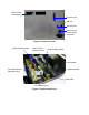
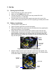
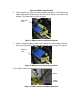
External Label Feed Opening Centronics Port USB port RS-232C Port Power Switch Power Supply Connector Figure 2: Printer rear view Ribbon Rewind Spindle Ribbon Tension Adjustment Knob Ribbon Supply Spindle Label Spindle Print Head Pressure Adjustment Knob Media Guide Bar Label Guide Print Head Lift Lever Figure 3: Printer interior view
2.4 Buttons, Indicators and adjustment knobs Power Indicator When the printer is in the power-on state, the Power indicator is lit. On-Line Indicator This green On-Line indicator is lit when the printer is ready. The On-Line indicator blinks when in PAUSE mode. Error Indicator The red Error indicator illuminates in the event of a printer error, such as memory full, carriage open, cutter error and so forth. MENU/SELECT Button Press the MENU button to enter printer setup mode.
the LCD display shows “Carriage Open” and the red Error light will come on. After closing the print head lift lever, the On-Line light will blink. Press the FEED button to re-register the label. Ribbon Tension Adjustment Knob The Ribbon Tension Adjustment Knob offers 6 levels of tension to adjust for different widths of ribbon. Turn the ribbon tension knob clockwise and you will hear a light click sound as the gear changes. The levels increase the tension from 0 to the tightest at 5.
3. Set Up 3.1 Setting Up the Printer 1. 2. 3. 4. 3.2 Place the printer on a flat, secure surface Make sure the POWER switch is off Connect the printer to the computer with the provided RS-232C, Centronics/Parallel, or USB cable Plug the power cord into the power supply connector at the rear of the printer, and then plug the power cord into a properly grounded power outlet Ribbon Installation 1. 2. 3. 4.
Figure 6: Ribbon under Pint Had 6. Pull the paper core up to the rewind spindle and slide it on. Slide both the ribbon and rewind spindle all the way to be flush with the case side of the spindle. The Wasp logo will face up again Flush with Case Figure 7: Ribbon placed onto Rewind Spindle 7. Roll the rewind spindle by hand until some of the actual ribbon shows in the front of the printer. The Wasp logo will roll over the top of the spindle.
3.3 Label Roll Installation 1. 2. 3. 4. Open the printer panels and the print head lift lever Rotate the Label Guide clockwise away from the Media Guide Bar Insert a new label roll into the label spindle Pull labels leading edge forward under the black media guide bar, through the gap/black mark sensor and place the label leading edge onto the Platen Roller Label Spindle Print Head Lever Platen Roller Label Guide Media Guide Bar Figure 10: Insert a label roll into label spindle.
3.4 Peel-off Sensor Installation (Sold Separately) 1. Turn the printer off 2. Open the lower front panel 3. Snap the peel-off sensor onto the bar that is under the print head pressure adjustment knobs horizontally Bar Peel-off sensor Figure 12: Peel Sensor attached to bar Socket for Peel-off sensor Figure 13: Peel Socket 4. Plug the Peel-off sensor into the socket by sliding it along the bar into the socket Figure 14: Peel Sensor into Socket 5. Close the panels and turn the printer back on 6.
3.5 Loading Label For Peel-off Mode 1. Open the front and top printer doors 2. Open the print head left lever 3. Pull several inches of labels out through the front of the printer and remove the label(s) from the backing 4. Feed the label backing between the platen roller and the silver peeler roller then press the MENU button several times to advance the label backing through the rollers. 5. Either advance the backing or roll back the labels to take the slack out of the media.
3.6 Self-test To initiate the self-test mode, press the MENU button to advance the selection to Printer Test. Press the EXE button to enter the submenu and press the MENU button to advance the selection to Printer Config. Press EXE button to print the printer’s internal settings. During self-test, a check pattern is used to check the performance of the thermal print head.
ASCII Data Hex decimal data related to left column of ASCII data Figure 18: Printout of dump mode
4. Calibration There are two power-on button combinations to initialize the printer settings and to calibrate sensors on the W606. 4.1 Printer Initialization Printer Initialization will restore printer settings to defaults. Do this if labels are printing incorrectly and all other solutions have failed to solve the problem.
To initialize the printer: 1. Turn off the printer power 2. Hold down the PAUSE and FEED buttons and turn on the printer power 3. Release the buttons once the Power, On-Line, and Error lights are lit Note: The printing method, thermal transfer or direct thermal printing, will be set automatically at the activation of printer power by checking for the ribbon. If there is no ribbon the printer will go into direct thermal printing mode.
4.3 Troubleshooting Guide The following guide lists the most common problems that may be encountered when operating this bar code printer. If the printer still does not function after all suggested solutions have been invoked, please contact the Customer Service. Condition No ribbon No paper Poor printing quality Reasons Solutions 1. Out of ribbon 2. The ribbon is installed incorrectly. 3. The ribbon sensor is not been calibrated. 1. Out of labels 2. The label is installed incorrectly. 3.
5. Printer Maintenance The printer should be cleaned regularly to maintain high quality printing. 5.1 Cleaning the Print Head 1. 2. 3. 4. 5. 6. 7. Switch off and unplug the printer Open the printer cover Open the print head lift lever Remove the ribbon. (If loaded) Rub the Wasp Thermal Printer Cleaning Pen Part# 633808441012 tip across the print head several times Do not close the print head until the alcohol evaporates Reload the ribbon, close the print head lift lever and close the printer cover 5.
6. Support and Warranty 6.1 Product Support If you experience any problems with your Wasp printer that you are unable to resolve, use our online support site to register and report the problem then call for technical assistance at (214) 547-4100, Monday through Friday, 8:00 AM – 5:00 PM Central Standard Time. You must register to be eligible for technical support. Our web site is www.waspbarcode.
Appendix 1: LCD Control Panel Operation Map Speed 2 "/se c *3"/se c 4"/sec 6"/sec 5 (*8) y Densit 1. Prin t Setu p 0 to 1 on Directi *0 Mode * Tear Offse 5"/sec 1 n Peel O n O Cutter Cutter Batch (*0) 0~999 t nce X Refere (*0) 0~999 nce Y (*0) 0~999 Refere Exit Auto. Gap al Gap Manu 2. or C Sens alib. line Auto B e al Blin Manu Auto. n Ribbo bon al Rib Manu Exit Lang. lish * Eng Polsk i Simpli fied C hines e hinese ional C Tradit ese Japan etup tem S 3.
y Countr etup tem S 3. Sys p 2 Setu RS23 * 001 002 003 031 032 039 038 036 034 033 041 042 044 045 046 061 055 049 048 047 351 358 e * Non Parity it Data B *8 *1 2 Baud 2400 4800 *9600 57600 56000 38400 19200 it(s) Exit ults re Defa Exit File Lis t mory ail. Me Mng 4. File ment Av ile(s) F Delete : DRAM KB free 512 H: FLAS B free 1000K l. All E: De PAUS xit E : FEED Exit onfig Print C e Off p Mod * Dum st ter Te 5.