WLS8600 Reference Manual
Wasp Barcode Technologies 1400 10th Street Plano, Texas USA 75074 ©2000-2013 Wasp Barcode Technologies, Inc. (an unpublished work provided under license).
CONTENTS 1 INTRODUCTION .......................................................................................... 1 2 2.1 2.2 2.3 2.4 2.5 2.6 INSTALLATION ............................................................................................ 2 WLS8600 Interface Cable Connections ........................................................ 2 RS-232 Connection ....................................................................................... 4 USB....................................................
WLS8600 4.3.1 4.3.2 4.4 4.4.1 4.4.2 4.5 4.5.1 4.5.2 4.5.3 4.5.4 4.5.5 4.6 4.6.1 4.6.2 4.6.3 4.7 4.7.1 4.8 4.9 4.10 4.11 4.11.1 4.12 Header/Terminator Selection .................................................................... 100 Define Special Key Sequence................................................................... 101 Power Save ............................................................................................... 109 Sleep State .......................................................
NOTES iii
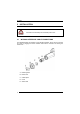
WLS8600 GENERAL VIEW WLS8600 READER LEDs Cable Connector Trigger Laser Output Window Figure A – WLS8600 Series Reader iv
INTRODUCTION 1 INTRODUCTION Wasp Barcode Technologies renews its range of industrial laser scanners introducing the WLS8600 family. Robustness and ergonomics remain unsurpassed: clearly audible beeper and bright "good read" LEDs for areas where noise levels are normally high; the aim mode, which helps point to the right code, has now been extended to the whole family.
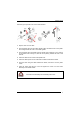
WLS8600 2 INSTALLATION Connections should always be made with power OFF! CAUTION 2.1 WLS8600 INTERFACE CABLE CONNECTIONS The WLS8600 reader incorporates a multi-standard interface, which can be connected to a Host by plugging the correct interface cable into the connector and closing the cable cover. A. Rubber gasket B. Plastic boot C. Cable spacer D. Cover E.
INSTALLATION Follow the given procedure for correct cable insertion: Align 1 3 2 5 6 Notch 4 7 Arrow Tab Slip the cover over the cable. Push the plastic boot into the rubber gasket. Take care that the tab on the plastic boot is aligned with the notch in the rubber gasket. Push the plastic boot and gasket into the handle. Ensure that the “Front” marking on the plastic boot is facing out, with the arrow pointing towards the front of the scanner.
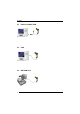
WLS8600 2.2 RS-232 CONNECTION 2.3 USB 2.
INSTALLATION 2.5 WEDGE CONNECTION 2.
WLS8600 3 CONFIGURATION 3.1 3.1.1 CONFIGURATION METHODS Reading Configuration Barcodes This manual can be used for complete setup and configuration of your reader by following the setup procedures in this chapter (see par. 3.2 for an overview). If you wish to change the default settings, this manual provides complete configuration of your reader in an easy way. To configure your reader: 1) Open the folded page in Appendix C with the hex-numeric table and keep it open during the device configuration.
CONFIGURATION 3.2 SETUP PROCEDURES For WLS8600 Series readers, follow the setup procedures in pars. 3.3, and 3.4. Proceed as shown in the following diagram: BEGIN SETUP Follow the procedure indicated below. 1. Restore default parameters Scan the Restore Default barcode at section 3.3, WLS8600 Setup. 2. Scan the interface code Go to section 3.4, Interface Selection and choose the appropriate barcode for your application. END SETUP Your reader is now ready to read barcodes using the default settings.
WLS8600 3.3 1. WLS8600 SETUP Read the restore default parameters code below. Restore WLS8600 Default Ì$+$*oÎ After reading the above code, go to par. 3.4 Interface Selection.
CONFIGURATION 3.4 INTERFACE SELECTION Read the interface selection code for your application. RS-232 Standard Ì$+CP0$-$Î POS TERMINALS Nixdorf Mode A Ì$+CM2EC0$->Î Fujitsu Ì$+CM1$-ÈÎ ICL Mode Ì$+CM0$-ÃÎ For POS terminal default settings refer to par. 4.12.
WLS8600 WEDGE IBM AT or PS/2 PCs Ì$+CP500$-aÎ IBM XT Ì$+CP503$-vÎ PC Notebook Ì$+CP505$-ÈÎ IBM SURE1 Ì$+CP506$-$Î IBM Terminal 3153 Ì$+CP504$-}Î IBM Terminals 31xx, 32xx, 34xx, 37xx: To select the interface for these IBM Terminals, read the correct KEY TRANSMISSION code. Select the KEYBOARD TYPE if necessary (default = advanced keyboard).
CONFIGURATION WEDGE (CONTINUED) ALT MODE The ALT-mode selection allows barcodes sent to the PC to be interpreted correctly independently from the Keyboard Nationality used. You do not need to make a Keyboard Nationality selection. (default = Num Lock Unchanged). Make sure the Num Lock key on your keyboard is ON.
WLS8600 3.5 USB READER CONFIGURATION The USB interface is compatible with the following Operating Systems: Windows 98 (and later) Mac OS 8.0 (and later) IBM POS for Windows 4690 Operating System USB Start-up As with all USB devices, upon connection, the Host performs several checks by communicating with the device. During this phase normal operations are suspended (the LED on the WLS8600 reader blinks).
CONFIGURATION USB USB-KBD Ì$+UA03$-:Î USB-KBD-ALT-MODE Ì$+UA04$-@Î USB-KBD-APPLE Ì$+UA05$-FÎ USB-COM* Ì$+UA02$-4Î USB-IBM-Table Top Ì$+UA00$-(Î USB-IBM-Hand Held Ì$+UA01$-.Î * When configuring USB-COM, the relevant files and drivers must be installed from the USB Device Installation software. Contact WASP Technical Support for more information.
WLS8600 3.6 CHANGING DEFAULT SETTINGS Once your reader is setup, you can change the default parameters to meet your application needs. Refer to the preceding paragraphs for initial configuration in order to set the default values and select the interface for your application. In this manual, the configuration parameters are divided into logical groups making it easy to find the desired function based on its reference group.
RS-232 PARAMETERS All WLS8600 Series readers BAUD RATE PARITY DATA BITS STOP BITS HANDSHAKING ACK/NACK PROTOCOL FIFO INTER-CHARACTER DELAY RX TIMEOUT SERIAL TRIGGER LOCK 1. Read the Enter Configuration code ONCE, available at the top of each page. 2. Read configuration codes from the desired groups. = Read the code and follow the procedure given 3.
Enter Configuration Ì$+;Î Exit and Save Configuration RS-232 Ì$-?Î BAUD RATE 300 baud ÌCD1XÎ 600 baud ÌCD2[Î 1200 baud ÌCD3^Î 2400 baud ÌCD4aÎ 4800 baud ÌCD5dÎ 9600 baud ÌCD6gÎ 19200 baud ÌCD7jÎ 38400 baud ÌCD8mÎ PARITY none ÌCC0SÎ even parity ÌCC1VÎ odd parity ÌCC2YÎ 16
Enter Configuration Ì$+;Î Exit and Save Configuration RS-232 Ì$-?Î DATA BITS 7 bits ÌCA0OÎ 8 bits ÌCA1RÎ 9 bits ÌCA2UÎ STOP BITS 1 stop bit ÌCB0QÎ 2 stop bits ÌCB1TÎ HANDSHAKING disable ÌCE0WÎ hardware (RTS/CTS) ÌCE1ZÎ software (XON/XOFF) ÌCE2]Î RTS always ON ÌCE3`Î See par. 4.1.1 for details.
Enter Configuration Exit and Save Configuration Ì$+;Î RS-232 Ì$-?Î ACK/NACK PROTOCOL disable ÌER0sÎ enable ÌER1vÎ See par. 4.1.2 for details. FIFO disable ÌEC0UÎ enable ÌEC1XÎ See par. 4.1.3 for details.
Enter Configuration Ì$+;Î Exit and Save Configuration RS-232 Ì$-?Î RX TIMEOUT timeout control in reception from Host ÌCL5Î Read 2 numbers from the table where: 00 = TIMEOUT disabled 01-99 = TIMEOUT from .1 to 9.9 seconds rx timeout 5 seconds See par. 4.1.4 for details.
USB PARAMETERS USB-COM USB-KBD USB-IBM Handshaking, Ack/Nack protocol, FIFO, Inter-character delay, Rx timeout, Serial trigger lock Keyboard nationality, FIFO, Inter-character delay, Inter-code delay, USB keyboard speed No parameter selection required. 1. Read the Enter Configuration code ONCE, available at the top of each page. 2. Read configuration codes from the desired groups. = Read the code and follow the procedure given 3.
Enter Configuration Ì$+;Î Exit and Save Configuration USB-COM Ì$-?Î HANDSHAKING disable ÌCE0WÎ hardware (RTS/CTS) ÌCE1ZÎ software (XON/XOFF) ÌCE2]Î RTS always ON ÌCE3`Î See par. 4.1.1 for details. ACK/NACK PROTOCOL disable ÌER0sÎ enable ÌER1vÎ See par. 4.1.2 for details. FIFO disable ÌEC0UÎ enable ÌEC1XÎ See par. 4.1.3 for details.
Enter Configuration Ì$+;Î Exit and Save Configuration USB-COM Ì$-?Î INTER-CHARACTER DELAY delay between characters transmitted to Host ÌCK3Î Read 2 numbers from the table where: 00 = DELAY disabled 01-99 = DELAY from 1 to 99 milliseconds delay disabled RX TIMEOUT timeout control in reception from Host ÌCL5Î Read 2 numbers from the table where: 00 = TIMEOUT disabled 01-99 = TIMEOUT from .1 to 9.9 seconds rx timeout 5 seconds See par. 4.1.4 for details.
Enter ConfiguratioN Ì$+;Î Exit and Save Configuration USB-KBD Ì$-?Î KEYBOARD NATIONALITY Not Available for USB-KBD-ALT-MODE Interface This parameter default value is restored through the Interface Selection code and not Restore Default.
Enter Configuration Ì$+;Î Exit and Save Configuration USB-KBD Ì$-?Î The Japanese and Eastern Block Keyboard Nationality selections are valid only for IBM AT compatible PCs. Japanese ÌFJ8|Î Russian (Latin) ÌFJ9ÃÎ Russian (Cyrillic) ÌFJA0Î Hungarian ÌFJB3Î Slovenian, Croatian, Serbian (Latin) ÌFJC6Î Romanian ÌFJD9Î Czech Republic ÌFJE<Î FIFO disable ÌEC0UÎ enable ÌEC1XÎ See par. 4.1.3 for details.
Enter ConfiguratioN Exit and Save Configuration Ì$+;Î Ì$-?Î USB-KBD INTER-CHARACTER DELAY delay between characters transmitted to Host ÌCK3Î Read 2 numbers from the table where: 00 = DELAY disabled 01-99 = DELAY from 1 to 99 milliseconds delay disabled INTER-CODE DELAY delay between codes transmitted to Host ÌFG.
WEDGE PARAMETERS KEYBOARD NATIONALITY CAPS LOCK CAPS LOCK AUTO-RECOGNITION NUM LOCK INTER-CHARACTER DELAY INTER-CODE DELAY KEYBOARD SETTING WEDGE CONTROL CHARACTER EMULATION 1. Read the Enter Configuration code ONCE, available at the top of each page. 2. Read configuration codes from the desired groups. = Read the code and follow the procedure given 3.
Enter Configuration Ì$+;Î Exit and Save Configuration WEDGE Ì$-?Î KEYBOARD NATIONALITY Belgian ÌFJ7yÎ English (UK) ÌFJ4pÎ French ÌFJ2jÎ German ÌFJ3mÎ Italian ÌFJ1gÎ Spanish ÌFJ6vÎ Swedish ÌFJ5sÎ USA ÌFJ0dÎ 27
Enter Configuration Ì$+;Î Exit and Save Configuration WEDGE Ì$-?Î The Japanese and Eastern Block Keyboard Nationality selections are valid only for IBM AT compatible PCs. Japanese ÌFJ8|Î Russian (Latin) ÌFJ9ÃÎ Russian (Cyrillic) ÌFJA0Î Hungarian ÌFJB3Î Slovenian, Croatian, Serbian (Latin) ÌFJC6Î Romanian ÌFJD9Î Czech Republic ÌFJE<Î CAPS LOCK caps lock OFF ÌFE0ZÎ caps lock ON ÌFE1]Î Select the appropriate code to match your keyboard caps lock status.
Enter Configuration Exit and Save Configuration Ì$+;Î Ì$-?Î WEDGE CAPS LOCK AUTO-RECOGNITION (IBM AT COMPATIBLE ONLY) disable ÌFP0pÎ enable ÌFP1sÎ NUM LOCK toggle num lock ÌFL1kÎ num lock unchanged ÌFL0hÎ This selection is used together with the Alt Mode interface selection for AT or Notebook PCs.
Enter Configuration Exit and Save Configuration Ì$+;Î WEDGE Ì$-?Î INTER-CODE DELAY delay between codes transmitted to Host ÌFG.Î Read 2 numbers from the table where: 00 = DELAY disabled 01-99 = DELAY from 1 to 99 seconds delay disabled KEYBOARD SETTING ALPHANUMERIC KEYBOARD SETTING The device (reader or cradle) can be used with terminals or PCs with various keyboard types and nationalities through a simple keyboard setting procedure.
WEDGE Some ASCII characters may be missing as this depends on the type of keyboard: these are generally particular characters relative to the various national symbologies. In this case: • The first 4 characters (Shift, Alt, Ctrl, and Backspace) can only be substituted with keys not used, or substituted with each other. • characters can be substituted with other single symbols (e.g. "SPACE") even if not included in the barcode set used.
Enter Configuration Exit and Save Configuration Ì$+;Î Ì$-?Î WEDGE CONTROL CHARACTER EMULATION Ctrl + Shift + Key ÌFO0nÎ Ctrl + Key ÌFO1qÎ 32
PEN EMULATION OPERATING MODE MINIMUM OUTPUT PULSE CONVERSION TO CODE 39 OVERFLOW OUTPUT LEVEL IDLE LEVEL INTER-BLOCK DELAY 1. Read the Enter Configuration code ONCE, available at the top of each page. 2. Read configuration codes from the desired groups. 3. = Default value Read the Exit and Save Configuration code ONCE, available at the top of each page.
PEN EMULATION The operating mode parameters are complete commands and do not require reading the Enter and Exit configuration codes. OPERATING MODE interpret mode Ì$]8Î Interprets commands without sending them to the decoder. transparent mode Ì$[4Î Sends commands to the decoder without interpreting them.
Enter Configuration Ì$+;Î Exit and Save Configuration PEN EMULATION Ì$-?Î MINIMUM OUTPUT PULSE high resolution code emulation 200 µs ÌDG0\Î 400 µs ÌDG1_Î 600 µs ÌDG2bÎ 800 µs ÌDG3eÎ 1 ms ÌDG4hÎ 1.2 ms low resolution code emulation ÌDG5kÎ See par. 4.2.1 for details.
Enter Configuration Exit and Save Configuration Ì$+;Î Ì$-?Î PEN EMULATION CONVERSION TO CODE 39 disable conversion to Code 39 ÌDA0PÎ Transmits codes in their original format. enable conversion to Code 39 ÌDA1SÎ Converts codes read into Code 39 format. See par. 4.2.2 for details. CONVERSION TO CODE 39 AND CODE 128 enable conversion to Code 39 ÌDA1SÎ Converts codes read into Code 39 format. enable conversion to Code 128 ÌDA0PÎ Converts codes read into Code 128 format. See par. 4.2.
Enter Configuration Exit and Save Configuration Ì$+;Î Ì$-?Î PEN EMULATION OUTPUT LEVEL normal ÌDD0VÎ (white = logic level 0) inverted ÌDD1YÎ (white = logic level 1) See par. 4.2.4 for details. IDLE LEVEL normal ÌDE0XÎ (black level) inverted ÌDE1[Î (white level) See par. 4.2.4 for details. INTER-BLOCK DELAY delay between character blocks transmitted to Host ÌCK3Î Read 2 numbers from the table where: 00 = DELAY disabled 01-99 = DELAY from .1 to 9.9 seconds delay disabled See par. 4.2.
DATA FORMAT NOT FOR PEN INTERFACES CODE IDENTIFIER CUSTOM CODE IDENTIFIER HEADER TERMINATOR SPECIAL KEYS FIELD ADJUSTMENT FIELD ADJ. CHARACTER CODE LENGTH TX CHARACTER REPLACEMENT 1. Read the Enter Configuration code ONCE, available at the top of each page. 2. Read configuration codes from the desired groups. = Read the code and follow the procedure given 3.
DATA FORMAT CODE IDENTIFIER TABLE CODE AIM STANDARD WASP STANDARD Custom 2/5 interleaved 2/5 industrial 2/5 normal 5 bars 2/5 matrix 3 bars EAN 8 EAN 13 UPC A UPC E EAN 8 with 2 ADD ON EAN 8 with 5 ADD ON EAN 13 with 2 ADD ON EAN 13 with 5 ADD ON UPC A with 2 ADD ON UPC A with 5 ADD ON UPC E with 2 ADD ON UPC E with 5 ADD ON Code 39 Code 39 Full ASCII CODABAR ABC CODABAR Code 128 EAN 128 ]Iy N ]Xy P ]Sy O ]Xy Q ]E4 A ]E0 B ]Xy C ]Xy D ]E5 J ]E6 K ]E1 L ]E2 M ]Xy F ]Xy G ]Xy H ]Xy I ]Ay V ]Ay W ]Fy R ]X
Enter Configuration Exit and Save Configuration Ì$+;Î Ì$-?Î DATA FORMAT CODE IDENTIFIER disable ÌEB0SÎ Wasp standard ÌEB1VÎ AIM standard ÌEB2YÎ custom ÌEB3\Î CUSTOM CODE IDENTIFIER define custom code identifier(s) ÌEH/Î Read the above code. (Code Identifiers default to Wasp standard, see table on previous page). Select the code type from the code table in Appendix B for the identifier you want to change. You can define 1 or 2 identifier characters for each code type.
Enter Configuration Ì$+;Î Exit and Save Configuration Ì$-?Î DATA FORMAT HEADER no header ÌEA00*Î one character header ÌEA01.Î two character header ÌEA022Î three character header ÌEA036Î four character header ÌEA04:Î five character header ÌEA05>Î six character header ÌEA06BÎ seven character header ÌEA07FÎ eight character header ÌEA08JÎ After selecting one of the desired Header codes, read the character(s) from the HEX table. Valid characters are in the range 00-FE.
Enter Configuration Ì$+;Î Exit and Save Configuration Ì$-?Î DATA FORMAT TERMINATOR no terminator ÌEA10-Î one character terminator ÌEA111Î two character terminator ÌEA125Î three character terminator ÌEA139Î four character terminator ÌEA14=Î five character terminator ÌEA15AÎ six character terminator ÌEA16EÎ seven character terminator ÌEA17IÎ eight character terminator ÌEA18MÎ After selecting one of the desired Header codes, read the character(s) from the HEX table.
Enter Configuration Ì$+;Î Exit and Save Configuration DATA FORMAT Ì$-?Î Available only for Wedge IBM AT-PS/2 and USB-KBD Interfaces It is necessary to define each Special Key by following the procedure given in par. 4.3.2. NOTE Select one or more of the following Special Keys according to your needs.
Enter Configuration Exit and Save Configuration Ì$+;Î Ì$-?Î DATA FORMAT FIELD ADJUSTMENT disable field adjustment ÌEF0[Î Field adjustment allows a number of characters n, to be added to or subtracted from the barcode read. The adjustment can be different for each enabled code type. To define the field adjustment: Read the enable field adjustment code: enable field adjustment ÌEF+Î Select the code type from the Code Identifier Table in Appendix B.
Enter Configuration Ì$+;Î Exit and Save Configuration DATA FORMAT Ì$-?Î FIELD ADJUSTMENT CHARACTER Read the field adjustment character code: field adjustment character ÌEG-Î Read the hexadecimal value corresponding to the character you want to use for field adjustment. Valid characters are in the range 00-FE. For Wedge and USB-KBD interfaces, it is also possible to read the Special Key(s) on page 42.
Enter Configuration Ì$+;Î Exit and Save Configuration DATA FORMAT Ì$-?Î CHARACTER REPLACEMENT disable character replacement ÌEO0mÎ This parameter allows up to three characters to be replaced from the barcode read. These substitutions are stored in memory.
Enter Configuration Exit and Save Configuration Ì$+;Î Ì$-?Î DATA FORMAT Example: The following strings define: 1. First Character Replacement: substitution in Code 39 barcodes of all occurrences of the 0 character with the 1 character. 2. Second Character Replacement: substitution in Code 39 barcodes of all occurrences of the A character with the B character.
POWER SAVE SLEEP STATE ENTER SLEEP TIMEOUT 1. Read the Enter Configuration code ONCE, available at the top of each page. 2. Read configuration codes from the desired groups. = Read the code and follow the procedure given 3. 48 = Default value Read the Exit and Save Configuration code ONCE, available at the top of each page.
Enter Configuration Ì$+;Î Exit and Save Configuration POWER SAVE Ì$-?Î SLEEP STATE disable ÌBQ0nÎ enable ÌBQ1qÎ See par. 4.4.1 for details. ENTER SLEEP TIMEOUT enter sleep timeout ÌBR@Î Read 2 numbers in the range 00-99: 00 = Enter Sleep state immediately 01-99 = corresponds to a max. 9.9 sec. delay before entering the Sleep state. enter sleep timeout = 0.6 sec. See par. 4.4.2 for details.
READING PARAMETERS TRIGGER TYPE TRIGGER SIGNAL TRIGGER CLICK TRIGGER-OFF TIMEOUT FLASH MODE READS PER CYCLE SAFETY TIME BEEPER INTENSITY BEEPER TONE BEEPER TYPE BEEPER LENGTH GOOD READ SPOT DURATION AIMING SYSTEM 1. Read the Enter Configuration code ONCE, available at the top of each page. 2. Read configuration codes from the desired groups. = Read the code and follow the procedure given 3.
Enter Configuration Ì$+;Î Exit and Save Configuration READING PARAMETERS Ì$-?Î TRIGGER TYPE hardware trigger ÌBK1eÎ Restores TRIGGER MODE software trigger ÌBK0bÎ Enables FLASH MODE always on ÌBK3kÎ TRIGGER SIGNAL trigger active level ÌBA0NÎ trigger active pulse ÌBA1QÎ See par. 4.5.1 for details. TRIGGER CLICK disable ÌBc0+Î enable ÌBc1.Î See par. 4.5.2 for details.
Enter Configuration Ì$+;Î Exit and Save Configuration Ì$-?Î READING PARAMETERS TRIGGER-OFF TIMEOUT trigger-off timeout ÌBD$Î Read 2 numbers in the range 00-99: 00 = disables the trigger-off timeout 01-99 = corresponds to a max. 99-sec. delay after the trigger press to allow the reader to turn off automatically. trigger-off timeout disabled See par. 4.5.3 for details. FLASH MODE "FLASH" ON duration ÌBB0PÎ "FLASH" OFF duration ÌBB1SÎ Read 2 numbers in the range 01-99: 01 to 99 = from .1 to 9.
Enter Configuration Ì$+;Î Exit and Save Configuration READING PARAMETERS Ì$-?Î SAFETY TIME safety time ÌBE&Î Limits same code consecutive reading. Read 2 numbers in the range 00-99: 00 = no same code consecutive reading until reader is removed (no decoding) for at least 400 ms. 01-99 = timeout from .1 to 9.9 seconds before a consecutive read on same code. safety time = 0.5 sec See par. 4.5.5 for details.
Enter Configuration Ì$+;Î Exit and Save Configuration READING PARAMETERS Ì$-?Î BEEPER TONE tone 1 ÌBH0\Î tone 2 ÌBH1_Î tone 3 ÌBH2bÎ tone 4 ÌBH3eÎ BEEPER TYPE monotone ÌBJ0`Î bitonal ÌBJ1cÎ BEEPER LENGTH long ÌBI0^Î short ÌBI1aÎ 54
Enter Configuration Exit and Save Configuration Ì$+;Î READING PARAMETERS Ì$-?Î GOOD READ SPOT DURATION disable ÌBV0xÎ short ÌBV1{Î medium ÌBV2~Î long ÌBV3ÅÎ AIMING SYSTEM disabled ÌBj09Î enabled ÌBj1<Î 55
DECODING PARAMETERS INK SPREAD OVERFLOW CONTROL INTERDIGIT CONTROL DECODING SAFETY PUZZLE SOLVER™ Before changing these parameter values read the descriptions in par. 4.6. CAUTION 1. 2. 3. 56 Read the Enter Configuration code ONCE, available at the top of each page. Read configuration codes from the desired groups. = Default value Read the Exit and Save Configuration code ONCE, available at the top of each page.
Enter Configuration Ì$+;Î Exit and Save Configuration DECODING PARAMETERS Ì$-?Î INK SPREAD disable ÌAX0{Î enable ÌAX1~Î See par. 4.6.1 for details. OVERFLOW CONTROL disable ÌAW1|Î enable ÌAW0yÎ See par. 4.6.2 for details. INTERDIGIT CONTROL disable ÌAV0wÎ enable ÌAV1zÎ See par. 4.6.3 for details.
Enter Configuration Exit and Save Configuration Ì$+;Î Ì$-?Î DECODING PARAMETERS DECODING SAFETY one read ÌED0WÎ (decoding safety disabled) two reads ÌED1ZÎ three reads ÌED2]Î four reads ÌED3`Î Required number of good reads before accepting code. PUZZLE SOLVER™ disable ÌAU0uÎ enable ÌAU1xÎ In the case of damaged or poorly printed codes, this parameter allows reading multiple parts of the single code to reconstruct it.
CODE SELECTION AUTO-CONFIGURATION EAN/UPC FAMILY 2/5 FAMILY CODE 39 FAMILY CODE 128 FAMILY CODABAR FAMILY CODE 93 MSI CODE 11 CODE 16K CODE 49 GS1 DATABAR CODES 1. Read the Enter Configuration code ONCE, available at the top of each page. 2. Read configuration codes from the desired groups. 3. = Read the code and follow the procedure given = Default value Read the Exit and Save Configuration code ONCE, available at the top of each page.
Code selections may be performed according to two different procedures: Auto-configuration, allowing an automatic recognition and selection of the code families to be read; - Manual configuration, requiring configuration and selection of each code family to be read. AUTO-CONFIGURATION The following codes do not require reading the Enter and Exit configuration codes.
Enter Configuration Exit and Save Configuration Ì$+;Î CODE SELECTION Ì$-?Î DISABLE ALL CODE FAMILIES ÌAZ0ÃÎ The reader allows up to 10 code selections. This does not limit the number of CODES enabled to 10, as it depends on the code family. NOTE SINGLE SELECTIONS = • ONE combination code from the EAN family • ONE code from the 2/5 family Example 5 code selections: 1. 2/5 Interleaved 2. 2/5 Industrial 3. Code 128 + EAN 128 4. Code 39 Full ASCII + Code 32 5. UPC A/UPC E 6. etc.
Enter Configuration Ì$+;Î Exit and Save Configuration CODE SELECTION Ì$-?Î EAN/UPC FAMILY disable the family ÌAA0MÎ Read the desired family code NOTE: Since the EAN/UPC without ADD ON code selection is enabled by default, to correctly enable another selection, first disable the family.
Enter Configuration Ì$+;Î Exit and Save Configuration CODE SELECTION Ì$-?Î WITH ADD ON 2 ONLY EAN 8/EAN 13 ÌAAK7Î UPC A/UPC E ÌAAM=Î WITH ADD ON 5 ONLY EAN 8/EAN 13 ÌAAL:Î UPC A/UPC E ÌAAN@Î WITH AND WITHOUT ADD ON EAN/UPC with and without ADD ON no Autodiscrimination ÌAA8Ad03Î EAN/UPC Autodiscrimination ADD ON by Prefix ÌAA8Ad19Î By setting the EAN/UPC Autodiscrimination ADD ON by Prefix, the desired prefixes must be selected by reading the corresponding codes given in the following secti
Enter Configuration Exit and Save Configuration Ì$+;Î Ì$-?Î CODE SELECTION SELECT EAN/UPC PREFIXES NOTE When scanning the following codes, barcodes starting with the selected prefixes will be read and transmitted only if the ADD ON is present. If no ADD ON is found, the barcode will not be read. Barcodes starting with different characters are read regardless of ADD ON presence and transmitted always without ADD ON.
Enter Configuration Exit and Save Configuration Ì$+;Î CODE SELECTION Ì$-?Î Example: The following string allows reading and transmitting with ADD ON all EAN/UPC starting with the 434/439, 977 and 978 prefixes: 1. EAN/UPC Autodiscrimination ADD ON by Prefix. 2. 434/439: enables reading and transmission with ADD ON of all EAN/UPC barcodes starting with 434/439 prefixes. 3. 977: enables reading and transmission with ADD ON of all EAN/UPC barcodes starting with 977 prefix. 4.
Enter Configuration Exit and Save Configuration Ì$+;Î Ì$-?Î CODE SELECTION EAN/UPC CHECK DIGIT TX SELECTIONS For each code type in this family you can choose to transmit the check digit or not CHECK DIGIT TRANSMISSION NO CHECK DIGIT TRANSMISSION EAN 8 ÌAAG1oÎ EAN 8 ÌAAG0kÎ EAN 13 ÌAAH1rÎ EAN 13 ÌAAH0nÎ UPC A ÌAAI1uÎ UPC A ÌAAI0qÎ UPC E ÌAAJ1xÎ UPC E ÌAAJ0tÎ 66
Enter Configuration Ì$+;Î Exit and Save Configuration CODE SELECTION Ì$-?Î CONVERSION OPTIONS UPC E to UPC A conversion ÌAAAÄÎ UPC E to EAN 13 conversion ÌAABÇÎ UPC A to EAN 13 conversion ÌAACÊÎ EAN 8 to EAN 13 conversion ÌAAD"Î Enable only ISBN conversion ÌAP1nÎ Enable only ISSN conversion ÌAP2qÎ Enable both ISBN and ISSN conversion ÌAP3tÎ Disable both ISBN and ISSN conversion ÌAP0kÎ 67
Enter Configuration Ì$+;Î Exit and Save Configuration Ì$-?Î CODE SELECTION 2/5 FAMILY disable the family ÌAC0QÎ Read the desired family code Read a check digit selection Interleaved 2/5 ÌAC1TÎ CHECK DIGIT TABLE no check digit control Ì12Î Normal 2/5 (5 Bars) ÌAC2WÎ check digit control and transmission Ì23Î Industrial 2/5 (IATA) ÌAC3ZÎ check digit control without transmission Ì34Î Matrix 2/5 (3 Bars) ÌAC4]Î Read 4 numbers for the code length − − The pharmaceutical code below i
Enter Configuration Ì$+;Î Exit and Save Configuration CODE SELECTION Ì$-?Î CODE 39 FAMILY disables the family ÌAB0OÎ Read the desired family code Read a check digit selection CHECK DIGIT TABLE Standard Code 39 no check digit control Full ASCII Code 39 check digit control and transmission ÌAB1RÎ ÌAB2UÎ Ì12Î Ì23Î check digit control without transmission Ì34Î The pharmaceutical codes below are part of the Code 39 family but have no check digit selections.
Enter Configuration Ì$+;Î Exit and Save Configuration CODE SELECTION Ì$-?Î CODE 128 FAMILY disable the family ÌAI0]Î Read the desired family code Code 128 ÌAI11=Î control without transmission of check digit ISBT 128 ÌAI31CÎ enabling ISBT 128 automatically disables Puzzle Solver™. EAN 128 ÌAI21@Î control without transmission of check digit Transmit GS Before Code Code EAN 128 uses the ASCII character to separate a variable length code field from the next code field.
Enter Configuration Ì$+;Î Exit and Save Configuration Ì$-?Î CODE SELECTION CODE 93 disable the code ÌAK0aÎ Code 93 ÌAK1dÎ control without transmission of check digit CODABAR FAMILY disable the family ÌAD0SÎ Read the desired equality control code Standard Codabar Read a start/stop transmission selection START/STOP CHARACTER TRANSMISSION ÌAD113Î no start/stop character equality control no transmission Ì12Î Standard Codabar ÌAD127Î start/stop character equality control transmission
Enter Configuration Ì$+;Î Exit and Save Configuration Ì$-?Î CODE SELECTION The Codabar ABC code below uses a fixed start/stop character transmission selection. Codabar ABC ÌAD212)Î no start/stop character equality control but transmission.
Enter Configuration Ì$+;Î Exit and Save Configuration CODE SELECTION Ì$-?Î MSI disable the family ÌAE0UÎ Enable the code by selecting one of the check digit selections.
Enter Configuration Ì$+;Î Exit and Save Configuration CODE SELECTION Ì$-?Î CODE 11 disable the family ÌAG0YÎ Enable the code by selecting one of the check digit selections.
Enter Configuration Ì$+;Î Exit and Save Configuration CODE SELECTION Ì$-?Î CODE 16K disable the code ÌAJ0_Î Code 16K ÌAJ1bÎ To read stacked codes, simply move the reader over the code so that each line of the code is scanned. During this process a series of brief “ticks” indicates that reading is proceeding correctly. CODE 49 disable the code ÌAM0eÎ Code 49 ÌAM1hÎ To read stacked codes, simply move the reader over the code so that each line of the code is scanned.
Enter Configuration Exit and Save Configuration Ì$+;Î Ì$-?Î CODE SELECTION GS1 DATABAR™ CODES disable the family ÌAQ0mÎ DISABLE CODE disable GS1 DataBar Expanded Linear and Stacked ENABLE CODE ÌAQ10IÎ enable GS1 DataBar Expanded Linear and Stacked ÌAQ11MÎ disable GS1 DataBar Limited ÌAQ20LÎ enable GS1 DataBar Limited ÌAQ21PÎ disable GS1 DataBar 14 Linear and Stacked ÌAQ30OÎ enable GS1 DataBar 14 Linear and Stacked ÌAQ31SÎ To read stacked codes, simply move the reader over the code so th
ADVANCED FORMATTING NOT FOR PEN INTERFACES CONCATENATION ADVANCED FORMATTING Please follow the setup procedure carefully for these parameters. NOTE The Advanced Formatting parameters may not be compatible with the IBM USB POS interface selection. NOTE 1. 2. 3. Read the Enter Configuration code ONCE, available at the top of page. Read configuration codes precisely following the numbered procedure given.
Enter Configuration Ì$+;Î Exit and Save Configuration ADVANCED FORMATTING Ì$-?Î CONCATENATION disable ÌEI0aÎ enable ÌEI1dÎ Permits the concatenation of two codes defined by code type and length. It is possible to set a timeout for the second code reading and to define code transmission if the timeout expires. The order of transmission is CODE 1-CODE 2. Define Concatenation 1 Code 1 code ID ÌEK0eÎ Read the code type from the Code Identifier Table beginning in Appendix B.
Exit and Save Configuration ADVANCED FORMATTING 2 Ì$-?Î Code 2 code ID ÌEK1hÎ Read the code type from the Code Identifier Table beginning in Appendix B. code length ÌEL1jÎ Read a number in the range 01-99 from the Hex/Numeric Table. 3 Concatenation Result Code ID use code 1 ID ÌEN0kÎ use code 2 ID ÌEN1nÎ Since you can concatenate codes from different families, you must select the Code ID character of the resulting code.
Exit and Save Configuration ADVANCED FORMATTING no code transmitted after timeout ÌEM0iÎ only code 1 transmitted (if read) after timeout ÌEM1lÎ only code 2 transmitted (if read) after timeout ÌEM2oÎ either code 1 or code 2 transmitted after timeout ÌEM3rÎ 80 Ì$-?Î
ADVANCED FORMATTING ADVANCED FORMATTING Advanced formatting has been designed to offer you complete flexibility in changing the format of barcode data before transmitting it to the host system. This formatting will be performed when the barcode data meets certain criteria, which you will define in the following procedure. Up to 4 advanced code management formats can be defined and saved in memory.
Enter Configuration Ì$+;Î 1 Exit and Save Configuration ADVANCED FORMATTING Ì$-?Î Begin Format Definition begin Format 1 definition ÌHA0TÎ begin Format 2 definition ÌHA1WÎ begin Format 3 definition ÌHA2ZÎ begin Format 4 definition ÌHA3]Î 2 Match Code Type match code type ÌHB&Î Read the above code + the code type to match from the Code Identifier Table in Appendix B.
Exit and Save Configuration ADVANCED FORMATTING 4 Ì$-?Î Match with Predefined Characters no match ÌHD0HE00ÄÎ OR match with 1 character ÌHD1]Î match with a 2-character string ÌHD2`Î match with a 3-character string ÌHD3cÎ match with a 4-character string ÌHD4fÎ After selecting the predefined match code, read the character(s) from the HEX table. Range of characters = 00-FE. Example: Match code with the 2-character predefined string = "@@".
Exit and Save Configuration ADVANCED FORMATTING 5 Ì$-?Î Divide Code into Fields divide code into fields ÌHF.Î Read one number in the range 1 to 5 to divide the code into fields. 6 Define Code Fields define code fields Each code field length can be set by either: a) defining a field separator character to be found in the code itself. In this case you can choose to discard the code separator character or include it as the last character of the field.
Exit and Save Configuration ADVANCED FORMATTING Ì$-?Î DEFINE FIELD 1 BY: EITHER field separator ÌHG0`Î a) Read the field separator character from the HEX table. Range of characters = 00-FE. discard separator include separator Ì01Î Ì12Î OR match character ÌHG3iÎ b) Read the match character from the HEX table. Range of characters = 00-FE. OR field length ÌHG1cÎ c) Read two numbers in the range 01 to 99 to define the field length.
Exit and Save Configuration ADVANCED FORMATTING Ì$-?Î DEFINE FIELD 2 BY: EITHER field separator ÌHG0`Î a) Read the field separator character from the HEX table. Range of characters = 00-FE. discard separator include separator Ì01Î Ì12Î OR match character ÌHG3iÎ b) Read the match character from the HEX table. Range of characters = 00-FE. OR field length ÌHG1cÎ c) Read two numbers in the range 01 to 99 to define the field length.
Exit and Save Configuration ADVANCED FORMATTING Ì$-?Î DEFINE FIELD 3 BY: EITHER field separator ÌHG0`Î a) Read the field separator character from the HEX table. Range of characters = 00-FE. discard separator include separator Ì01Î Ì12Î OR match character ÌHG3iÎ b) Read the match character from the HEX table. Range of characters = 00-FE. OR field length ÌHG1cÎ c) Read two numbers in the range 01 to 99 to define the field length.
Exit and Save Configuration ADVANCED FORMATTING Ì$-?Î DEFINE FIELD 4 BY: EITHER field separator ÌHG0`Î a) Read the field separator character from the HEX table. Range of characters = 00-FE. discard separator include separator Ì01Î Ì12Î OR match character ÌHG3iÎ b) Read the match character from the HEX table. Range of characters = 00-FE. OR field length ÌHG1cÎ c) Read two numbers in the range 01 to 99 to define the field length.
Exit and Save Configuration ADVANCED FORMATTING Ì$-?Î DEFINE FIELD 5 BY: EITHER field separator ÌHG0`Î a) Read the field separator character from the HEX table. Range of characters = 00-FE. discard separator include separator Ì01Î Ì12Î OR match character ÌHG3iÎ b) Read the match character from the HEX table. Range of characters = 00-FE. OR field length ÌHG1cÎ c) Read two numbers in the range 01 to 99 to define the field length.
Exit and Save Configuration Ì$-?Î ADVANCED FORMATTING 7 First Additional Fixed Field no fixed field ÌHI0dÎ 1 character fixed field ÌHI1gÎ 2 character fixed field ÌHI2jÎ 3 character fixed field ÌHI3mÎ 4 character fixed field ÌHI4pÎ 5 character fixed field ÌHI5sÎ 6 character fixed field ÌHI6vÎ After selecting one of the Additional Fixed Field codes, read the corresponding character(s) from the HEX table. Range of characters = 00-FE.
Exit and Save Configuration ADVANCED FORMATTING 8 Ì$-?Î Second Additional Fixed Field no fixed field ÌHJ0fÎ 1 character fixed field ÌHJ1iÎ 2 character fixed field ÌHJ2lÎ 3 character fixed field ÌHJ3oÎ 4 character fixed field ÌHJ4rÎ 5 character fixed field ÌHJ5uÎ 6 character fixed field ÌHJ6xÎ After selecting one of the Additional Fixed Field codes, read the corresponding character(s) from the HEX table. Range of characters = 00-FE.
Exit and Save Configuration Ì$-?Î ADVANCED FORMATTING 9 Field Transmission number of fields to transmit ÌHK8Î Read one number in the range 1 to 7 for the number of fields to transmit. Include only fields to be transmitted. Field Order Transmission Read the codes corresponding to the fields to transmit in the order in which they are to be transmitted. A field can be transmitted more than once. See example.
Exit and Save Configuration ADVANCED FORMATTING 10 Ì$-?Î Standard Formatting do not apply standard formatting ÌHL0jÎ apply standard formatting ÌHL1mÎ After performing Advanced Formatting on the barcode read, Standard Formatting (Headers, Code Length, Code ID, Terminators) can be applied to the message to be transmitted.
Enter Configuration Ì$+;Î Exit and Save Configuration ADVANCED FORMATTING Ì$-?Î Enable Advanced Format no Advanced Formats enabled ÌHN0nÎ enable Advanced Format 1 ÌHN11NÎ enable disable ÌHN10JÎ Advanced Format 2 ÌHN21QÎ enable disable ÌHN20MÎ Advanced Format 3 ÌHN31TÎ enable ÌHN41WÎ 94 disable ÌHN30PÎ Advanced Format 4 disable ÌHN40SÎ
Enter Configuration Ì$+;Î Exit and Save Configuration ADVANCED FORMATTING Ì$-?Î No Match Result clear data - no transmission ÌHO0pÎ transmit data using standard format ÌHO1sÎ This selection determines the action to be taken when codes read do not conform to the advanced format requisites (no match). • Codes not matching can be ignored, cleared from memory and not transmitted. • Codes not matching can be transmitted using the Standard formatting (Headers, Code Length, Code ID, Terminators).
WLS8600 4 REFERENCES 4.1 4.1.1 RS-232 PARAMETERS Handshaking Hardware handshaking: (RTS/CTS) The RTS line is activated by the decoder before transmitting a character. Transmission is possible only if the CTS line (controlled by the Host) is active.
REFERENCES 4.1.2 ACK/NACK Protocol WLS8600 Readers This parameter sets a transmission protocol in which the Host responds to the reader after every code transmitted. The Host sends an ACK character (06 HEX) in the case of good reception or the NACK character (15 HEX) requesting re-transmission, in the case of bad reception. data WLS8600 cable Host ACK or NACK ACK/NACK enabled If the reader does not receive an ACK or NACK, transmission is ended after the RX Timeout (see par. 4.1.4).
WLS8600 4.1.4 RX Timeout When the RS-232 interface is selected, the Host can be used to configure the device by sending it command strings (see Appendix A). This parameter can be used to automatically end data reception from the Host after the specified period of time. If no character is received from the Host, after the timeout expires, any incomplete string (any string not terminated by ) is flushed from the device buffer. 4.2 PEN PARAMETERS 4.2.
REFERENCES 4.2.4 Output and Idle Levels The following state diagrams describe the different output and idle level combinations for Pen emulation: idle bar OUTPUT: Normal space IDLE: Normal barcode output bar OUTPUT: Normal idle space IDLE: Inverted barcode output space OUTPUT: Inverted IDLE: Normal bar black white black white space idle white white idle barcode output OUTPUT: Inverted black bar IDLE: Inverted barcode output black Output and Idle Levels 4.2.
WLS8600 4.3.1 Header/Terminator Selection The header/terminator selection is not effected by the reading of the restore default code. In fact, header and terminator default values depend on the interface selection: RS-232: no header, terminator CR-LF WEDGE: no header, terminator ENTER These default values are always restored through the reading of RS-232 or WEDGE interface selection code, see chapter 2.
Enter Configuration Exit and Save Configuration Ì$+;Î 4.3.2 Ì$-?Î Define Special Key Sequence The Special Key(s) for Wedge IBM AT-PS/2 and USB-KBD interface users can be associated with a sequence of keyboard keys that otherwise could not be selected, i.e. ALT + F6, SHIFT + F1.
WLS8600 2.
REFERENCES 3. Select the character to be associated with the Special Key sequence by reading the codes corresponding to the 3 character values from Appendix C. Then, read the Exit and Save Configuration code above to complete the Special Key sequence.
WLS8600 KEYB CHAR : ; < = > ? @ [ \ ] ^ _ ’ (accent) a b c d e f g h i j k l m n o p q r s t u v 104 ITA USA S S 049 S 041 061 S 045 S 061 04E A 04C A 054 00E A 05B S 055 S 04A 01C 032 021 023 024 02B 034 033 043 03B 042 04B 03A 031 044 04D 015 02D 01B 02C 03C 02A 04C 04C S 041 055 S 049 S 04A S 01E 054 05D 05B S 036 S 04E 00E 01C 032 021 023 024 02B 034 033 043 03B 042 04B 03A 031 044 04D 015 02D 01B 02C 03C 02A FR 049 041 061 055 S 061 S 03A A 045 A 02E A 03E A 04E A 046 03E A 03D 015 032 021 023
MESSAGE FORMATTING KEYB CHAR w x y z { | } ~ ITA USA FR BE 01D 022 035 01A S 00E - 01D 022 035 01A S 054 S 05D S 05B S 00E 01A 022 035 01D A 025 A 036 A 055 A 01E 01A 022 035 01D A 046 A 016 A 045 A 04A DE 01D 022 01A 035 052 04C 054 04E UK ES SW JP 01D 022 035 01A S 054 S 061 S 05B S 05D 01D 022 035 01A A 052 A 016 A 05D - 01D 022 035 01A A 03D A 061 A 045 A 05B 01D 022 035 01A S 05B S 06A S 05D S 055 To use upper case letters, it is necessary to read one of the SHIFT commands from step
WLS8600 KEYB ITA CHAR Up arrow Down arrow Left arrow Right arrow Esc Ctrl right € SPACE USA FR BE DE UK ES SW JP 275 275 275 275 275 275 275 275 275 272 272 272 272 272 272 272 272 272 26B 26B 26B 26B 26B 26B 26B 26B 26B 274 076 274 076 274 076 274 076 274 076 274 076 274 076 274 076 274 076 214 A 02E 029 214 A 02E 029 214 A 024 029 214 A 024 029 214 A 024 214 A 025 214 A 02E 029 214 A 02E 214 029 If Caps Lock Auto-Recognition is disabled, it is neces
MESSAGE FORMATTING 2. the following example allows defining Special Key 2 as CTRL + S (upper case): enter configuration Read Ì$+;Î define Special Key 2 + ÌFQ9D2BÎ codes from Appendix C corresponding to the character value for s (lower case) 01B + 3.
WLS8600 2. the following example allows setting Special Key 2 (defined in example 2 above) as header: enter configuration Read 3. Ì$+;Î one character header + ÌEA01.Î special key 2 + Ì9DÆÎ exit & save configuration + Ì$-?Î the following example allows setting Special Key 3 (defined in example 3 above) as header: enter configuration Read 4. Ì$+;Î one character header + special key 3 ÌEA01.
MESSAGE FORMATTING 4.4 4.4.1 POWER SAVE Sleep State When using interfaces other than USB, this mode allows the µP in the reader to enter a “Sleep” state for minimum power consumption.This command is only valid when hardware trigger type is selected. Before entering Sleep mode, the following are verified: • no commands coming from Host • no data being transmitted to Host • Enter Sleep Timeout ended (see par. 4.4.2) To exit Sleep mode press the trigger.
WLS8600 4.5 READING PARAMETERS 4.5.1 Trigger Signal This mode determines how the reading phase is controlled when the hardware trigger operating mode is selected: • trigger active level: the reader goes ON when the trigger is pressed and goes OFF when it is released • trigger active pulse: the reader goes ON at the first trigger press and goes OFF only at a second press 4.5.2 Trigger Click When enabled, it activates a "click" sound upon each trigger pressure. 4.5.
MESSAGE FORMATTING When one read per cycle is selected, the device decodes only one code during the ON period and immediately turns the reader OFF. It is only possible to read another code when the next ON time occurs. In multiple reads per cycle, the ON period is extended so that the device can continue decoding codes until an OFF event occurs. For software trigger mode, the flash on period is immediately reset after each read and therefore extended.
WLS8600 4.6.3 Interdigit Control The interdigit control parameter verifies the interdigit spacing for code families Code 39 and Codabar. 4.7 4.7.1 ADVANCED FORMATTING Match Conditions Selecting an Advanced Formatting and specifying a Match restriction (Code Type, Code Length, Predefined Characters) the code will be transmitted according to the order of the defined formats.
MESSAGE FORMATTING 4.8 CONFIGURATION EDITING COMMANDS The following commands carry out their specific function and then exit the configuration environment. Command Description Ì$+$*oÎ Restore WLS8600 reader default configuration (see the relative Quick Reference Guide for default settings) Ì$+$!KÎ Transmit the WLS8600 software release Ì$+$&_Î Transmit WLS8600 reader configuration in ASCII format. This command is not effective with Pen emulation interface.
WLS8600 4.9 CUSTOM DEFAULT CONFIGURATION Read the following code to set the reader user-defined configuration as custom default configuration: Save User-defined Configuration as Custom Default Ì$+$0ÂÎ Read the following code whenever you need to restore the custom default configuration: Restore Custom Default Configuration Ì$+$1$Î 4.
MESSAGE FORMATTING 4.11 CONFIGURATION COPYING COMMANDS 4.11.1 Copy WLS8600 Series Procedure: Connect the master (correctly configured reader) and the slave (reader to be configured) together through two RS-232 serial interface cables and external power supply. RS-232 Cables: CAB471 & CAB472 Power Supply: PG5 Using the slave reader, read the Restore Default barcode and then the RS-232 interface barcode from chapter 3 of this manual or from the Quick Reference Guide.
WLS8600 4.12 DEFAULT PARAMETERS FOR POS TERMINALS The default values of the RS-232 and Data Format parameters for POS terminals are listed in the following table: NIXDORF Mode A FUJITSU ICL Mode 9600 Odd 8 1 Hardware (RTS/CTS) Disabled Disabled Disabled 9.9 sec Disabled 9600 None 8 1 None Disabled Enabled Disabled 2 sec Disabled 9600 Even 8 1 RTS always ON Disabled Enabled Disabled 9.
TECHNICAL FEATURES 5 5.1 TECHNICAL FEATURES WLS8600 Electrical Features Power Supply Max.
WLS8600 5.2 STATUS INDICATORS The scanner has two indicator LEDs and a Beeper. They signal several operating conditions, which are described in the tables below.
TECHNICAL FEATURES 5.3 READING TABLE WLS8600 mil Typical reading distance with good quality codes 5 2.1 - 13.3 cm / 0.8 - 5.2 in 7,5 3.5 - 24.2 cm / 1.4 - 9.5 in 10 2.9 - 42.8 cm / 1.1 - 16.8 in 13 2.3 - 55.1 cm / 0.9 - 21.7 in 20 6.3 - 78.5 cm / 2.5 - 30.9 in 40 2.5 - 97.8 cm / 1.0 - 38.
WLS8600 A HOST CONFIGURATION STRINGS SERIAL CONFIGURATION STRINGS SPECIAL CONFIGURATION COMMANDS DESCRIPTION Enter Configuration Exit and Save Configuration Restore Default Transmit Software Release (not for PEN emulation) Transmit Device Configuration in ASCII (not for PEN emulation) Set Custom Default Restore Custom Default STRING $+ $$+$* $+$! $+$& $+$0 $+$1 These commands do not require $-.
HOST CONFIGURATION STRINGS DESCRIPTION Baud Rate RS-232 300 600 1200 2400 4800 9600 19200 38400 Parity none even odd Data Bits 7 8 9 Stop Bits 1 2 Handshaking disable RTS/CTS XON/XOFF RTS always On ACK/NACK Protocol disable enable FIFO disable enable Inter-character Delay (ms) RX Timeout (100 ms) Serial Trigger Lock disable enable and select characters STRING CD1 CD2 CD3 CD4 CD5 CD6 CD7 CD8 CC0 CC1 CC2 CA0 CA1 CA2 CB0 CB1 CE0 CE1 CE2 CE3 ER0 ER1 EC0 EC1 CK00 - CK99 CL00 - CL99 CR0 CR1ab a = Hex values
WLS8600 DESCRIPTION USB-COM Handshaking ACK/NACK Protocol FIFO Inter-character Delay (ms) RX Timeout (100 ms) Serial Trigger Lock USB-KBD Keyboard Nationality (not for USB-KBD-ALT-MODE) Keyboard Nationality (IBM AT compatible only) FIFO Delays USB Keyboard Speed USB STRING disable enable CE0 CE1 CE2 CE3 ER0 ER1 EC0 EC1 CK00 - CK99 CL00 - CL99 CR0 CR1ab Belgian English (UK) French German Italian Spanish Swedish USA Japanese Russian (Latin) Russian (Cyrillic) Hungarian Slovenian, Croatian, Serbian
HOST CONFIGURATION STRINGS DESCRIPTION Keyboard Nationality Keyboard Nationality (IBM AT compatible only) Caps Lock Caps Lock Auto-Recognition (IBM AT compatible only) Num Lock Delays Control Character Emulation DESCRIPTION Operating Mode WEDGE Belgian English (UK) French German Italian Spanish Swedish USA Japanese Russian (Latin) Russian (Cyrillic) Hungarian Slovenian, Croatian, Serbian (Latin) Romanian Czech Republic caps Lock ON caps Lock OFF disable enable toggle num lock num lock unchanged Inter
WLS8600 PEN (continued) DESCRIPTION Idle Level Overflow Inter-block Delay (100 ms) normal inverted narrow overflow medium overflow wide overflow DATA FORMAT NOT FOR PEN EMULATION INTERFACES DESCRIPTION Code Identifier Custom Code Identifier Headers Terminators disable Wasp standard AIM standard custom no header one character two characters three characters four characters five characters six characters seven characters eight characters no terminator one character two characters three characters four
HOST CONFIGURATION STRINGS DESCRIPTION Code Length Tx DATA FORMAT (continued) NOT FOR PEN EMULATION INTERFACES Field Adjustment Field Adjustment Character Character Replacement not transmitted transmitted in variable-digit format transmitted in fixed 4-digit format disable right addition left addition right deletion left deletion disable character replacement first character replacement second character replacement third character replacement STRING EE0 EE1 EE2 EF0 EFa0d EFa1d EFa2d EFa3d EGe EO0 EO1a
WLS8600 DESCRIPTION Sleep State Enter Sleep Timeout (100 ms) DESCRIPTION Trigger Type Trigger Signal Trigger Click Trigger-off Timeout (s) FLASH ON (100 ms) FLASH OFF (100 ms) Reads per Cycle Safety Time (100 ms) Beeper Intensity Beeper Tone Beeper Type Beeper Length Good Read Spot Duration Aiming System 126 POWER SAVE disable enable READING PARAMETERS software trigger hardware trigger always on trigger active level trigger active pulse disable enable one read multiple reads very low intensity low
HOST CONFIGURATION STRINGS DESCRIPTION Ink-spread Overflow Control Interdigit Control Puzzle SolverTM Decoding Safety DECODING PARAMETERS disable enable disable enable disable enable disable enable one read two reads three reads four reads CODE SELECTION DESCRIPTION DISABLE ALL FAMILY CODES EAN/UPC disable EAN/UPC family EAN 8/EAN 13/UPC A/UPC E without ADD ON with ADD ON with and without ADD ON EAN 8/EAN 13 without ADD ON with ADD ON 2 ONLY with ADD ON 5 ONLY with ADD ON 2 AND 5 UPC A/UPC E without ADD
WLS8600 CODE SELECTION (continued) DESCRIPTION UPC A check digit transmission disable enable UPC E check digit transmission disable enable conversions UPC E to UPC A UPC E to EAN 13 UPC A to EAN 13 EAN 8 to EAN 13 ISBN Conversion codes enable ISBN enable ISSN enable ISBN and ISSN disable ISBN and ISSN Code 39 disable Code 39 family Standard no check digit control check digit control and transmission check digit control without transmission Full ASCII no check digit control check digit control and transmissi
HOST CONFIGURATION STRINGS CODE SELECTION (continued) DESCRIPTION Codabar disable Codabar family Standard no start/stop character equality control nor transmission no start/stop character equality control but transmission start/stop character equality control but no transmission start/stop character equality control and transmission ABC Codabar no start/stop character equality control but transmission Codabar ABC forced concatenation code length start/stop character case in transmission lower case upper cas
WLS8600 DESCRIPTION Code 11 Code 16K Code 49 GS1 DataBar™ Codes 130 CODE SELECTION (continued) disable the family no check Type C with tx Type C no tx Type K with tx Type K no tx Type C and K with tx Type C and K no tx disable enable disable enable disable the family disable GS1 DataBar Expanded Linear and Stacked enable GS1 DataBar Expanded Linear and Stacked disable GS1 DataBar Limited enable GS1 DataBar Limited disable GS1 DataBar Linear and Stacked enable GS1 DataBar Linear and Stacked STRING AG0 A
B CODE IDENTIFIER TABLE 2/5 Interleaved ÌNOÎ 2/5 Industrial ÌPQÎ 2/5 normal 5 bars ÌOPÎ 2/5 matrix 3 bars ÌQRÎ EAN 8 ÌABÎ EAN 13 ÌBCÎ UPC A ÌCDÎ UPC E ÌDEÎ EAN 8 with 2 ADD ON ÌJKÎ EAN 8 with 5 ADD ON ÌKLÎ EAN 13 with 2 ADD ON ÌLMÎ EAN 13 with 5 ADD ON ÌMNÎ UPC A with 2 ADD ON ÌFGÎ 131
WLS8600 UPC A with 5 ADD ON ÌGHÎ UPC E with 2 ADD ON ÌHIÎ UPC E with 5 ADD ON ÌIJÎ Code 39 ÌVWÎ Code 39 Full ASCII ÌWXÎ CODABAR ÌRSÎ ABC CODABAR ÌSTÎ Code 128 ÌTUÎ EAN 128 ÌklÎ Code 93 ÌUVÎ CIP/39 ÌYZÎ CIP/HR ÌefÎ Code 32 ÌXYÎ ISBT 128 ÌfgÎ 132
CODE IDENTIFIER TABLE MSI ÌZ[Î Code 16K ÌpqÎ Code 11 ÌbcÎ Code 49 ÌqrÎ GS1 DATABAR Expanded Linear and Stacked ÌtuÎ GS1 DATABAR Limited ÌvwÎ GS1 DATABAR 14 Linear and Stacked ÌuvÎ 133
WLS8600 C HEX AND NUMERIC TABLE CHARACTER TO HEX CONVERSION TABLE 134 char hex char hex char hex NUL SOH STX ETX EOT ENQ ACK BEL BS HT LF VT FF CR SO SI DLE DC1 DC2 DC3 DC4 NAK SYN ETB CAN EM SUB ESC FS GS RS US SPACE ! " # $ % & ' ( ) 00 01 02 03 04 05 06 07 08 09 0A 0B 0C 0D 0E 0F 10 11 12 13 14 15 16 17 18 19 1A 1B 1C 1D 1E 1F 20 21 22 23 24 25 26 27 28 29 * + , .
NOTES
NOTES
NOTES
www.waspbarcode.com Wasp Barcode Technologies 1400 10th Street Plano, Texas USA 75074 ©2000-2013 Wasp Barcode Technologies, Inc .. 820022890 (Rev.