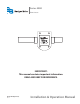
Series 4000 Flow Sensor ® IMPORTANT: This manual contains important information. READ AND KEEP FOR REFERENCE. 872121-EN (April 2012) Rev.
Series 4000 Page ii April 2012
Installation & Operation Manual CONTENTS INTRODUCTION . . . . . . . . . . . . . . . . . . . . . . . . . . . . . . . . . . . . . . . . . . . . . . . . . . . . . . . . . 5 MODELS . . . . . . . . . . . . . . . . . . . . . . . . . . . . . . . . . . . . . . . . . . . . . . . . . . . . . . . . . . . . . . 5 MECHANICAL INSTALLATION . . . . . . . . . . . . . . . . . . . . . . . . . . . . . . . . . . . . . . . . . . . . . . . . . 6 General . . . . . . . . . . . . . . . . . . . . . . . . . . . . . . . . . . . . . .
Series 4000 Page iv April 2012
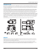
Installation & Operation Manual INTRODUCTION Data Industrial® nonmagnetic flow sensors by Badger Meter provide an accurate measurement of liquid flow. The Series 4000 flow sensor covers applications for ½" to 1" pipe sizes and a wide range of pressure/temperature specifications. When used in conjunction with Badger Meter Series 1500, Series 2000, and Series 300 electronics, the measurement may be displayed or transmitted as a rate or total.
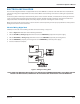
Series 4000 MECHANICAL INSTALLATION General The accuracy of flow measurement for all flow measuring devices is highly dependent on proper location of the sensor in the piping system. Irregular flow velocity profiles caused by valves, fittings, pipe bends, etc. can lead to inaccurate overall flow rate indications even though local velocity measurement may be accurate.
Installation & Operation Manual ELECTRICAL INSTALLATION The Series 4000 digital transmitter is supplied with 20 feet of 20 AWG three conductor cable with drain wire and shield. The Series 4000 analog unit is supplied with 30 inches of cable. Make electrical wiring connections according to accepted trade practices. An electrical junction box may be attached directly to the sensor electronic module, or mounted in the vicinity of the sensor.
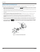
Series 4000 Impeller Assembly and Shaft Replacement The following tools are required for the replacement of the impeller and shaft: 5/32" Allen wrench, flat blade screwdriver, torque driver in “in-lb” with 5/32" male hex adapter. Units are factory calibrated at 12in-lbs. 1. Depressurize the pipe on which the sensor is to be serviced. WHILE SYSTEM IS UNDER PRESSURE. DO NOT REMOVE SOCKET HEAD CAP SCREWS 2.
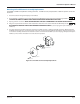
Installation & Operation Manual Detecting Coil and Electronic Assembly Replacement A #1 Phillips screwdriver is required for servicing electronics. It is not necessary to depressurize or drain the system to service the electronics. 1. Disconnect sensor wiring from display or transmitter. 2. Using a Phillips screwdriver, loosen and remove the two #4 Phillips head screws and accompanying hardware. LETTING ELECTRONIC ASSEMBLY DROP FROM SENSOR COULD DAMAGE DETECTING COIL. 3.
Series 4000 REPLACEMENT PART NUMBERS Impeller 08010 Coil Kit (for digital output unit only) (1) coil (1) retaining plate (2) #6 screws 711333 O-Ring Kit PVDF units only for use with Unions O-Ring Kit, EPDM O-Rings, 1/2" for 20 mm Union 4003OKE O-Ring Kit, EPDM O-Rings, 3/4" for 25 mm Union 4013OKE O-Ring Kit, EPDM O-Rings, 1" for 32 mm Union 4023OKE O-Ring Kit, Viton O-Rings, 1/2" for 20 mm Union 4003OKV O-Ring Kit, Viton O-Rings, 3/4" for 25 mm Union 4013OKV O-Ring Kit, Viton O-Rings, 1" for
Installation & Operation Manual Example: 400P 2RK COVER MATERIAL PVC 2RK PVDF 3RK COVER O-RING Viton® EPDM Kalrez ® Food Grade Silicon Neoprene® Chemraz ® Teflon® Encapsulated Viton® Teflon Encapsulated Silicon Buna N Aflas ® Kalrez Cover/TFE Encapsulated Viton SHAFT Zirconia Ceramic Hastalloy ® C Tungsten Carbide Titanium Monel® 316 Stainless Steel Tantalum Sapphire IMPELLER Tefzel® BEARING UHMWPE Tefzel® Teflon - 0 0 2 2 0 1 2 3 4 5 6 7 8 9 A 0 1 2 3 5 6 7 9 2 1 2 3 Figure 5: Series 4000 Impeller
Series 4000 CALIBRATION If you are replacing an existing Series 4000 sensor and have already calibrated your flow monitor, no calibration changes are necessary. For installation of a new flow monitor, please refer to the calibration instructions in the flow monitor manual. The Series 4000 flow sensor, like all impeller or turbine flow meters, operates by converting kinetic energy (in the flow stream) into rotation (of an impeller).
Installation & Operation Manual PVC schedule 80 pipe of the appropriated diameter is installed upstream of the sensor, and a similar 5 to 10 diameter lengths downstream. PVDF sensor calibration is based on flow through industry standard PVDF pipe. Similar action should be taken if the PVDF sensor is used in a system based on other piping technologies. CALIBRATION TABLE-DIGITAL OUTPUT The following table provides calibration and operational data for the various models of the Badger Series 4000 sensor.
Series 4000 SPECIFICATIONS Wetted Materials Sensor Housing and Enhancing Jet (If Applicable) PVC - Virgin polyvinyl chloride, type 1, grade 1 PVDF - Virgin polyvinylidene fluoride Sensor # Mat'l Nom. Pipe Pipe OD Pipe ID K Offset GPM min GPM max Hz min Hz max 400200 PVC 1/2 #80 .0840 in 401200 PVC 3/4 #80 1.050 in 0.546 0.413 0.3496 0.75 15.00 1.46 35.97 0.824 0.5735 0.2638 1.75 35.00 2.78 402000 PVC 1 #80 60.76 1.315 in 0.957 0.6134 0.1826 2.25 45.00 3.
Installation & Operation Manual O-Rings • Viton® • EPDM • Kalrez® • Silicon - food grade • Neoprene® • Chemraz® • Teflon® Encapsulated Viton Impeller Shafts • Zirconia Ceramic • Hastelloy® - C-276 • Tungsten Carbide - GE carboloy 883 colbalt binder • Titanium - titanium alloy 86Ti-6AL-6V-25A • Monel® - Grade K500 • Stainless Steel - 316 stainless steel • Tantalum - commercial grade Process Connections • PVC (virgin polyvinyl chloride, type 1, grade 1) schedule 80 tail pieces •
Series 4000 Linearity • +/- .7% of full scale over recommended design flow range • +/- 1.0% frequency to current conversion Transducer Power Digital Output Unit • Typically provided by Badger Meter flow monitor or transmitter. Any alternate supply must be of a resistancelimited type meeting the following constraints: • Supply voltage: 9 to 20 VDC • Supply current: 2mA maximum Analog Output Unit • 10 VDC minimum to 35 VDC maximum.
Installation & Operation Manual TROUBLESHOOTING General Primary consideration for troubleshooting a Series 4000 flow sensor is to first establish that the problem lies with the sensor and not with the electronic device connected to it. A simple way to help determine this is to substitute a known working sensor for the suspect unit. If the electronics react in an appropriate manner, you may conclude that the problem is sensor related.
Series 4000 7. If the sensor was working and a rebuild kit was installed due to a failure of the impeller or shaft and the sensor did not return to working order, check to ensure that the impeller was installed in the proper direction. If the impeller was installed backwards to the flow direction, no signal pulse will be generated even if the impeller spins freely. 8. Should you experience any other difficulties with the sensor, please consult the factory or your local representative.
Installation & Operation Manual (This page intentionally left blank.
Please see our website at www.badgermeter.com for specific contacts. www.badgermeter.com Data Industrial® is a registered trademark of Badger Meter, Inc. Other trademarks appearing in this document are the property of their respective entities. Due to continuous research, product improvements and enhancements, Badger Meter reserves the right to change product or system specifications without notice, except to the extent an outstanding contractual obligation exists. © 2012 Badger Meter, Inc.