Installation and Servicing Manual Wood Pellet Cast Iron Boiler MESys 4000 - 6000 Series Distributed by Maine Energy Systems Caution! Observe the safety instructions of this installation and maintenance manual before placing the boiler in operation. Danger! All installation, burner set-up and adjustment, and maintenance operations must be performed by a licensed service professional. The directions of this installation and maintenance manual must be followed precisely.
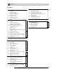
Contents Contents 1 1.1 1.2 1.3 1.3.1 1.3.2 1.3.3 1.4 1.5 Safety Considerations and Symbol Descriptions Regarding this Manual Explanation of Symbols Observe the following Symbols Installation Guidelines Boiler Room Guidelines Ash Removal Guidelines Tools, Materials and Accessories Disposal 2 2.1 2.2 2.3 2.3.1 2.3.2 2.4 2.5 2.6 2.7 2.8 2.8.1 2.8.2 2.8.3 2.8.4 2.8.5 2.8.
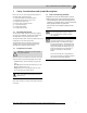
Safety Considerations and Symbol Descriptions 1 Safety Considerations and Symbol Descriptions Below is an overview of the integrated safety features of the MESys 4000 - 6000 Series boiler: 1.) Honeywell manual reset high limit aquastat 2.) Safeguard manual reset low water cut out 3.) Drop shaft burn back sensor 4.) External Auger resettable overload 5.) 15 Amp fast acting fuse 6.) 10 Amp circuit breaker 7.) Fuseable pellet feed hose 1.
1 1.3.1 Safety Considerations and Symbol Descriptions Installation Guidelines Caution: DANGER TO LIFE from electric shock. V Do not work on electrical components un less you have the required qualifications. V Prior to opening the burner door: follow Burner Installation Instructions, shut down the power supply by turning off the emergency shut-off switch or disengaging the heating system circuit breaker, to prevent from accidental reactivation. V Observe all applicable installation guidelines. 1.3.
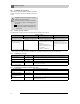
Safety Considerations and Symbol Descriptions Refer to Table 1 regarding wood pellet characteristics suitable for use with this pellet boiler system. Please check with your pellet fuel supplier regarding meeting these fuel requirements. Characteristic Premium Grade Only Pellet diameter 1/4" - 3/8" (6 – 10 mm) Pellet length 3/8" - 1" (10 – 25 mm) Ash content .2 – 1% 1 1.5 Disposal Please dispose of any trash in an environmentally V friendly fashion.
2 2 Product description Product description This Installation and Service Manual contains important information for the safe and intended installation, initial start-up and maintenance of this boiler. The wood pellet fired boiler MESys 4000 - 6000 Series is generally referred to below as a boiler. The installation and maintenance manual is provided for technicians who have been trained and have experience in working with heating systems and wood pellet fired installations. 2.
2 Product description 2.5 Product details The boiler is a wood pellet fired appliance with modulating burner control for boiler water temperature control. Caution: Risk of system damage from use of incorrect burner. Only use Janfire NH pellet burners which V meets the technical boiler requirements.
2 2.6 Product description Delivery contents Upon delivery, check that the packaging is complete and undamaged.
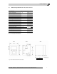
2 Product description 2.7 Dimensions Specifications for MESys 4000 - 6000 Series No. of Sections 4 6 Approx. Output (kW) 14 20 Approx.
Product description 2 2.8 Conditions for operation Maintaining the specified operating conditions will enable the boiler to provide a high level of reliability and long service life. Caution: Risk of system damage if operating conditions are not maintained. Irreversible damage to individual components of the boiler as a whole or the heating system may occur. The information supplied in this boiler manV ual and burner manual is binding and must be observed. 2.8.
Product description 2.8.4 2 Conditions for the boiler room and the environment Operating conditions Temperature in the boiler room relative humidity Dust/airborne particles Notes – Requirement in greater detail +40 to +104 °F max. 70 % No condensation or precipitation inside the boiler room Excessive dust inside the boiler room must be avoided when the boiler is operating, e. g.
3 3 Moving the boiler Moving the boiler This chapter details how to move the boiler safely. Caution: Risk of system damage from impact. Fragile components could be damaged. Observe the transport instructions on the V packaging. Protect boiler connections from damage and dirt if the boiler is not installed immediately. Dispose of packaging in an environmentally responsible manner. WARNING: Risk of injury from carrying heavy loads.
Installing the boiler 4 4 Installing the boiler This chapter details proper boiler installation. The individual steps involve: – 4.1 Wall clearances. – 4.2 Flue pipe installations. – 4.3 Fitting the water connections. – 4.4 Filling the heating system and checking for leaks. – 4.5 Mounting the Janfire NH Burner. Dimension A B – 4.6 Installing Boiler Jacket Panels. – 4.7 Installing the aquastat and burner sensors. C Caution: Risk of system damage from freezing.
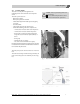
Installing the boiler 4 4.2 Burner door opening To open the burner door, electrically disconnect the burner first if burner is already mounted on the boiler. - Remove the 2 hex bolts (Fig. 4a, item 2) below the burner door opening. - Swing the burner door open - Now use top handle to open access door to flue passages. 4.3 Flue gas collector installation If not pre-assembled, install collector by following steps below: – Loosen the mounting nuts.
Installing the boiler V Install flue connections between boiler and chimney to Installing the flue pipe Danger: Risk of death from escaping flue gases. Installing V theIfflue pipe the resistance to flue gas flow is too great and/or the flue pipe diameter is smaller than the recommended size and/or the flue pipe is too short. V Install 6" vent pipe on flue collector and use high temp- erature sealant for air tight connection. Leakage leads to wrong CO2 measurement and wrong burner adjustment.
4 4.5 Installing the boiler Fitting the water connections Caution: Risk of system damage from leaking connections. Support the pipes to the boiler to prevent V them from being under stress. 4.5.1 Installing the B-kit Install the 1-1/4” x 3” nipple into the top rear connection V with the parallel thread into the boiler. V Install the 90° elbow into desired direction. Install supply manifold into the 90° elbow. (Fig. 5). V Install the P&T gauge into the 1/4” manifold connection.
Installing the boiler 4.6 Filling the heating system and checking for leaks The boiler is tested for leaks at the factory. Before putting the heating system into operation, it must be checked to ensure that no leaks will occur during operation. Caution: Risk of system damage from excess pressure when testing for leaks. Pressure, control and safety equipment may be damaged by excessive pressure.
4 4.7 Installing the boiler Mounting the Janfire NH burner Remove the Janfire burner from its box and verify the following components: Janfire NH burner V Wiring harness with plugs for feed auger operation. V Power wiring harness with plug for power supply to V burner. 3 pin connector with 2 sensors and corresponding wiring V (labeled boiler and outdoor). Second 3 pin connector for communication is not used. V Burner Installation and Service Manual.
Installing the boiler 4.8 Installing Boiler Jacket Panels Installation sequence, refer to Fig. 9: – – – – – – – – – 1 Front top cross bar (3) 2 Rear top cross bar (5) 3 Right hand side panel (2) 4 Left hand side panel (10) 5 Rear panel (4) 6 Top insulation blanket (not shown; embedded in top panels) 7 Front top cover (7) 8 Rear top cover (8) 10 Front cover (90) 6) Installation of remaining cover panels. – Slide the front top panel from the front with its tabs into the slots of the side panels.
4 4.9 Installing the boiler Installing the aquastat and burner sensors This pellet boiler/burner system is equipped with an outdoor sensor to provide outdoor temperature control for system efficiency optimization. The boiler is equipped with a 3/4” well for boiler water sensing near the boiler supply tapping. A Honeywell L4006E aquastat (Fig. 10a) is supplied as a manual reset high limit control to shut down burner in case of a high temperature condition.
5 ( C 5 Commissioning the heating system This chapter describes the initial start-up procedure following burner and pellet fuel supply installation. 5.2 Checking the safety valve Complete the start-up protocol during this process V (Chapter 5.6, page 23). V Make sure that no persons are in the discharge area of the Further information on boiler room layout and clearances, combustion air requirements and venting systems and boiler operational requirements can be found in Chapter 2.8, pg.
5 5.3 Commissioning the heating system Preparing the heating system for operation Adhere to all instructions contained in the Boiler Installation and Service Manual, Boiler Operating Manual and Burner Installation Manual. Specifically, adhere to all clearance requirements put forth in the Boiler Installation and Service Manual. V Check for ample pellet supply in the pellet fuel storage bin.
Commissioning the heating system 5.5 Notes on commissioning the pellet burner Allow burner to operate for 15 to 20 minutes before performing a combustion test. Earlier combustion tests can lead to incorrect readings as a result of burning off the sealing rope. We recommend rechecking the burner after a few weeks of operation. Incorrect burner adjustment can cause contamination of the boiler (e.g. soot), leading to low efficiency, high emissions, and a greater risk of service calls.
5 5.6 1. Commissioning the heating system Commissioning log (Initial and date the commissioning steps carried out) Commissioning operations Page Fill heating system and check for leaks 17 Comments ____________ psi – Heating system pressure 2. Readings taken Bring the system up to 15 - 20 psi operating pressure 21 Bleed heating system of air V ____________ psi Test functioning of pressure relief valve V Adjust expansion tank pressure (follow manufacturers’ V recommendations). 3.
Shutting down the heating system 6 6 Shutting down the heating system Caution: Risk of system damage from freezing. If the heating system has been turned off, it may freeze up in cold weather conditions. V Leave the heating system switched on as long as possible. Protect a disabled heating system from V freezing by draining the heating system and hot water pipes at the lowest point. V Padlock shut the emergency switch to prevent accidental operation of the pellet feeder system.
7 Heating system servicing 7 Heating system servicing 7.1 Why is regular maintenance important? Danger: Danger: Risk Risk of of death death from from electric electric shock. shock.
Heating system servicing 7.5 7 Cleaning the boiler The boiler must be cleaned every 2 - 3 months periodically by bushing the heating surfaces and baffles, and removal of ashes from the ash compartment and main combustion chamber. The use of an industrial grade, high temperature resistant shop vac simplifies the removal of ashes from the ash compartment and primary heating surfaces.
7 7.6 Heating system servicing Servicing and maintenance logs V Initial and date the servicing operations completed. The inspection and servicing logs can also be used as copy masters. Service work Page 1. Check general condition of heating system 2. Visual inspection and function check of the heating system 3.
7 1. Heating system servicing Date:______ Date:______ Date:______ Date:______ Date:______ Date:______ Date:______ Date:______ Date:______ Date:______ Date:______ Date:______ Date:______ Date:______ 1. 2. 3. 4. 5. 6. 7. 8. 9. 10. 1. 1. 2. 3. 4. 5. 6. 7. If any condition requiring maintenance work is identified in the course of servicing, that work must be carried out as necessary to ensure safe and proper operation.
Trouble Shooting 8 8 Trouble Shooting This Trouble shooting section is designed as an aid in identifying malfunctions of the system and provide corrective action steps. It is broken down by major system components to assist in problem identification and correction. The list is not all inclusive but will cover most typical scenarios.
9 9 Installation examples Installation examples The MESys 4000 - 6000 Series system can be installed in new applications and existing hot water based heating systems. The boiler system can also be combined with an existing hot water based heating system where now the pellet boiler is the primary heat source. In addition to space heating, the pellet system is ideally suited to provide domestic hot water by means of an indirect hot water tank. Watts 120°F domestic hot water tempering valve 9.
Installation Example 9 Fig. 12 Piping Diagram: Zoning w/pumps and dedicated DHW pump. Fig. 13 MESys 4000 - 6000 Series - Technical specifications are subject to change without prior notice.
Installation Examples 9 Cold DHW Fig. 14: Multiple zoning with zone valves. Fig. 15 MESys 4000 - 6000 Series - Technical specifications are subject to change without prior notice.
9 Installation Examples Fig. 16 : High and low temperature heating with injection loop. Fig. 17 34 MESys 4000 - 6000 Series- Technical specifications are subject to change without prior notice.
Installation Examples Fig. 18: Multiple high and low temp zones with mixing valve. Fig. 19 M ESys 4000 - 6000 Series - Technical specifications are subject to change without prior notice.
Installation Examples Fig. 20 Condensate protection piping Fig. 21 Condensate protection wiring M ESys 4000 - 6000 Series - Technical specifications are subject to change without prior notice.
10 Parts List 1 - Boiler block 2 - Flue collector assembly 3 - Boiler jacket 37 MESys 4000 - 6000 Series- Technical specifications are subject to change without prior notice.
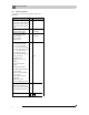
Parts lists 10 10 Parts lists The following parts are available from MESys. If there are several article numbers for one item number, the numbers for the various models are listed in the relevant columns. Otherwise the table shows the number of components for each model. MESys 4000 - 6000 Series - Technical specifications are subject to change without prior notice.
10 Parts lists Fig. 22 39 MESys 4000 - 6000 Series- Technical specifications are subject to change without prior notice.
10 Parts lists Fig. 23 MESys 4000 - 6000 Series- Technical specifications are subject to change without prior notice.
10 Parts List Fig. 24 - Accessories 41 MESys 4000 - 6000 Series- Technical specifications are subject to change without prior notice.
10 Parts List Fig. 25 - Safety Component Wiring Instructions *Required for storage bins with service access panels. MESys 4000 - 6000 Series- Technical specifications are subject to change without prior notice.
Maine Energy Systems, LLC One Parkway, P.O. Box 547 Bethel, ME 04217-0547 Phone: 207.824.NRGY (6749) www.maineenergysystems.com Maine Energy Systems, LLC reserves the right to make changes without notice due to continuing engineering and technological advances.