SXT Timer Supplemental Service Manual IMPORTANT: Fill in Pertinent Information on Page 3 for Future Reference
Table of Contents Job Specification Sheet.......................................................................................................................................... 3 Timer Features....................................................................................................................................................... 4 Timer Operation...................................................................................................................................................
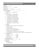
Job Specification Sheet Job Number: __________________ Model Number: ________________ Water Hardness: ___________________ ppm or gpg Capacity Per Unit: ______________ Mineral Tank Size: ___________ Diameter: ___________ Height: Salt Setting per Regeneration: _____________________________________________ 1. 2. Type of Timer: A. 7 Day or 12 Day B. Meter Initiated Meter Size: A. 3/4” Std Range (125 - 2,100 gallon setting) B. 3/4” Ext Range (625 - 10,625 gallon setting) C.
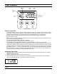
Timer Features Parameter Display Data Display PM Indicator Error/ Information Icon Flow Indicator Service Icon x1000 Indicator Programming Icon Extra Cycle Button Up Button Down Button Features of the SXT: • • • • • • • • Power backup that continues to keep time and the passage of days for a minimum of 48 hours in the event of power failure. During a power outage, the control goes into a power-saving mode.
Timer Features Queueing a Regeneration 1. Press the Extra Cycle button. The service icon will flash to indicate that a regeneration is queued. 2. To cancel a queued regeneration, press the Extra Cycle button. Regenerating Immediately Press and hold the Extra Cycle button for five seconds.
Timer Operation Meter Immediate Control A meter immediate control measures water usage and regenerates the system as soon as the calculated system capacity is depleted. The control calculates the system capacity by dividing the unit capacity (typically expressed in grains/unit volume) by the feedwater hardness and subtracting the reserve. Meter Immediate systems generally do not use a reserve volume.
Timer Operation Control Operation During A Power Failure The SXT includes integral power backup. In the event of power failure, the control shifts into a power-saving mode. The control stops monitoring water usage, and the display and motor shut down, but it continues to keep track of the time and day for a minimum of 48 hours. The system configuration settings are stored in a non-volatile memory and are stored indefinitely with or without line power.
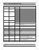
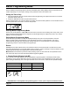
Master Programming Mode Chart Master Programming Options Abbreviation Parameter Option Abbreviation GAL DF VT CT Display Format Valve Type Control Type Number of Tanks Gallons Ltr Liters Cu Cubic Meters St1b Standard Downflow/Upflow Single Backwash St2b Standard Downflow/Upflow Double Backwash Fltr Filter UFbF Upflow Brine First Othr Other Fd Meter (Flow) Delayed FI Meter (Flow) Immediate tc Time Clock dAY NT Options Day of Week 1 Single Tank System 2 Two Tank System U1
Master Programming Mode Chart Master Programming Options FM K Flow Meter Type Meter Pulse Setting t0.7 3/4” Turbine Meter P0.7 3/4” Paddle Wheel Meter t1.0 1” Turbine Meter P1.0 1” Paddle Wheel Meter t1.5 1.5” Turbine Meter P1.5 1.5” Paddle Wheel Meter Gen Generic or Other Meter Meter pulses per gallon for generic/other flow meter NOTES: Some items may not be shown depending on timer configuration.
Master Programming Mode When the Master Programming Mode is entered, all available option setting displays may be viewed and set as needed. Depending on current option settings, some parameters cannot be viewed or set.. . Setting the Time of Day 1. Press and hold either the Up or Down buttons until the programming icon replaces the service icon and the parameter display reads TD. 2. Adjust the displayed time with the Up and Down buttons.
Master Programming Mode 2. Valve Type (Display Code VT) Press the Extra Cycle button. Use this display to set the Valve Type. The Valve Type setting specifies the type of cycle that the valve follows during regeneration. Note that some valve types require that the valve be built with specific subcomponents. Ensure the valve is configured properly before changing the Valve Type setting. This option setting is identified by “VT” in the upper left hand corner of the screen.
Master Programming Mode 5. Tank in Service (Display Code TS) Press the Extra Cycle button. Use this display to set whether tank one or tank two is in service. This option setting is identified by “TS” in the upper left hand corner of the screen. This parameter is only available if the number of tanks has been set to 2. There are two possible settings: Tank One in Service: Tank Two in Service: U1 U2 6. Unit Capacity (Display Code C) Press the Extra Cycle button. Use this display to set the Unit Capacity.
Master Programming Mode 8. Reserve Selection (Display Code RS) Press the Extra Cycle button. Use this display to set the Safety Factor. Use this display to select the type of reserve to be used in your system. This setting is identified by “RS” in the upper left-hand corner of the screen. The reserve selection parameter is only available if the control type has been set to one of the metered options. There are two possible settings. FS Safety Factor rc Fixed Reserve Capacity . . . . . 9.
Master Programming Mode 11. Day Override (Display Code DO) Press the Extra Cycle button. Use this display to set the Day Override. This setting specifies the maximum number of days between regeneration cycles. If the system is set to a timer-type control, the day override setting determines how often the system will regenerate. A metered system will regenerate regardless of usage if the days since last regeneration cycle equal the day override setting.
Master Programming Mode 14. Day of Week Settings Press the Extra Cycle button. Use this display to set the regeneration schedule for a system configured as a Day of Week control. The different days of the week are identified as D1, D2, D3, D4, D5, D6, and D7 in the upper left-hand corner of the display. Set the value to “ON” to schedule a regeneration or “OFF” to skip regeneration for each day. Use the Up and Down buttons to adjust the setting as needed.
Master Programming Mode 17. Meter Pulse Setting (Display Code K) Press the Extra Cycle button. Use this display to specify the meter pulse setting for a non-standard flow meter. This option setting is identified by “K” in the upper left-hand corner of the screen. Use the Up and Down buttons to enter the meter constant in pulses per unit volume.. . . . 18. Press the Extra Cycle button to save all settings and exit Master Programming Mode.
User Programming Mode User Programming Mode Options Abbreviation Parameter Description DO Day Override The timer’s day override setting RT Regeneration Time The time of day that the system will regenerate (meter delayed, timeclock, and day-of-week systems) H Feed Water Hardness The hardness of the inlet water - used to calculate system capacity for metered systems RC Reserve Capacity The fixed reserve capacity CD Current Day The current day of week NOTES: Some items may not be shown depend
User Programming Mode identified by “RC” in the upper left-hand corner of the screen.. . . . . . 6. Press the Extra Cycle button. Use this display to set the Current Day of the Week. This option setting is identified by “CD” in the upper left hand corner of the screen. . . . . . . 7. Press the Extra Cycle button to end User Programming Mode.
Diagnostic Programming Mode Diagnostic Programming Mode Options Abbreviation Parameter Description FR Flow Rate Displays the current outlet flow rate PF Peak Flow Rate Displays the highest flow rate measured since the last regeneration HR Hours in Service Displays the total hours that the unit has been in service VU Volume Used Displays the total volume of water treated by the unit RC Reserve Capacity Displays the system’s reserve capacity calculated from the system capacity, feedwater hard
Diagnostic Programming Mode 6. Press the Up button. Use this display to view the Reserve Capacity. This option setting is identified by “RC” in the upper left hand corner of the screen.. . . . . . 7. Press the Up button. Use this display to view the Software Version. This option setting is identified by “SV” in the upper left hand corner of the screen.. . . . . . 8. Press the Extra Cycle button to end Diagnostic Programming Mode.
Notes Page 21
2510 / 2750 / 2850s Timer Assembly 1 2 3 4 7 8 5 9 2 6 9A 9B 9C 9D Item No. Quantity Part No. Description 1.................... 1..................... 13881.......................BRACKET, HINGE TIMER 2.................... 2..................... 11384.......................SCREW, PHIL, 6-32 X 1/4 3.................... 1..................... 14265.......................CLIP, SPRING 4.................... 1..................... 27172.......................STAND-OFF, TIMER, 2510SXT, 2750SXT 5..............
9000/9100/9500 Twin Tank Timer Assembly 1 5 6 7 2 4 3 7A 7B 7C 7D Item No. Quantity Part No. Description 1.................... 1..................... 13881.......................BRACKET, HINGE TIMER 2.................... 2..................... 11384.......................SCREW, PHIL, 6-32 X 1/4 3.................... 1..................... 42732.......................BRACKET, TIMER, 9000SXT 4.................... 2..................... 13296.......................SCREW, HEX WSH, 6-20 X 1/2 5..........
3/4” Plastic Turbine Meter Assembly Item No. Quantity Part No. Description 1.................... 1..................... 19791-01..................Meter Cable Assy, Turbine/SXT 2.................... 2..................... 19569.......................Clip, Flow Meter 3.................... 2..................... 13314.......................Screw, Slot Ind Hex, 8-18 x .
3/4” Plastic Paddle Meter Assembly Item No. Quantity Part No. Description 1...................1.................... 13821.......................Body, Meter, 5600 2...................1.................... 13509.......................Impeller, Meter 3...................1.................... 13847.......................O-ring, -137, Std/560CD, Meter 4...................1.................... 14716.......................Meter Cap Assy, ET/NT 5...................4.................... 12473.......................
3/4” Brass Paddle Meter Assembly Item No. Quantity Part No. Description 1.................... 1..................... 11206.......................Gasket, Fitting 2.................... 1..................... 13942.......................Retainer, Nut 3.................... 1..................... 11207.......................Nut, Special, QC 4.................... 1..................... 13906.......................Body, Meter, 3/4” 5.................... 1..................... 13509.......................
1” Brass Paddle Meter Assembly Item No. Quantity Part No. Description 1.................... 1..................... 14959.......................Body, Meter, 2750 2.................... 1..................... 13882.......................Post, Meter Impeller 3.................... 1..................... 13509.......................Impeller, Meter 4.................... 1..................... 13847.......................O-ring, -137, Std/560CD, Meter 5.................... 1..................... 14716.............
Inline Plastic Turbine Meter Assembly Item No. Quantity Part No. Description 1.................... 1..................... 17542.......................Flow Straightener 2.................... 2..................... 40576.......................Clip, H, Plastic, 7000 3.................... 1..................... 40577.......................Turbine Meter Assy, 7000 4.................... 1..................... 41555.......................Body, Remote Meter 5.................... 2..................... 40951.......
1 1/2” Brass Paddle Meter Assembly Item No. Quantity Part No. Description 1.................... 1..................... 17569.......................Body, Meter, 2850/9500 2.................... 1..................... 13882.......................Post, Meter Impeller 3.................... 1..................... 13509.......................Impeller, Meter 4.................... 1..................... 13847.......................O-ring, -137, Std/560CD, Meter 5.................... 1..................... 14716....
3/4”, 1” or 1 1/2” Paddle Wheel Meter Cap Assembly Item No. Quantity Part No. Description 1.................... 1..................... 14716.......................Meter Cap Assy, NT 2.................... 1..................... 19121-01..................Meter Cable Assy, SXT, Paddle 6700XTR 3.................... 1..................... 13847.......................O-ring, -137, Std/560CD, Meter 4.................... 1..................... 17798.......................
2510SXT Wiring Diagram Page 31
2750SXT / 2850SXT Wiring Diagram Page 32
9000SXT / 9100SXT / 9500SXT Wiring Diagram Page 33
Troubleshooting Error Codes Note: Error codes appear on the In Service display. Error Code Probable Cause Recover and Resetting [Err 0] Drive motor is stalled Unplug the unit from the power source [Err 1] Drive motor is running continuously When power is restored to the unit, the Err _ display code clears. If the condition causing the error has not been resolved the Err _ code reappears in the four digit display. Do not attempt to troubleshoot this problem any further.
Service Assemblies Meter: 60086-50......... Meter Assy, 3/4”, Electronic 2510/6600/6700 60613.............. Meter Assy, 2750 Electronic 1” 60613-20......... Meter Assy, 2750, Electronic 1” BSP/Metric 60613NP......... Meter Assy, 2750, Electronic 1” Nickel Plated 60614.............. Meter Assy, 2850/9500, Electronic 1 1/2” Meter 60614NP......... Meter Assy, 2850/9500, Electronic 1 1/2” Meter, NP 60618.............. Meter Assy, Electronic, 3/4” 60619-20......... Meter Assy, 1 1/2” Elect BSP/Metric 60626......
P/N 42713 Rev.