
Use and Care Manual


-1-
How To Install The Tank
1. Find the fuse or circuit breaker
panel for your house. Turn off the
power to the well pump.
For your safety
,
the information
in this manual must be followed
to minimize the risk of electric
shock, property damage or
personal injury. Properly ground
to conform with all governing
codes and ordinances.
2. Open a faucet inside the house
as close to the tank as possible.
Drain the system as much as
possible by letting the water run
until it runs out.
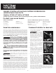
3. Close the ball or gate valve (this
is the valve that controls the
flow of water from the tank into
the plumbing system inside the
house) (Fig. 1)
4. Close the ball or gate valve on
the pump feed line, the pipe
through which the pump draws
water from the well into the
house. (Fig. 2) This stops water
from running back into the well.
5. Drain the pump system.
Place a bucket under the drain
nearest the existing tank. Or, run
a hose from the drain into a
bucket or floor drain. Loosen a
union coupling over the pump
using the pipe wrench and the
adjustable wrench. This will let
air into the system and let the
water run out. Loosen until the
water flows out. Let the water
run out of the system.
If there is no drain near the
tank, open the pipe union closest to the tank using the 12”
adjustable wrench or the 12” pipe wrench. If there are no
union couplings, use a pipe cutter to open the pipe. Insert a
coupling to re-close the system when you are done draining
the system. (Fig. 3)
INSTALLATION MANUAL FOR HORIZONTAL WELL SYSTEM TANKS
Models HT6HB, HT14HB and HT20HB
Keep this manual with the tank for future reference.
Part #: 9015-377 (07/12)
What You’ll Need
Before You Start
Always be sure to equip your well system with a proper Pressure
Relief Valve. This should be capable of discharging the full output of
the pump at or below the maximum working pressure of the lowest
rated component in the system. See the owner’s manual for your
pump for output information. This is vital for safe operation of the
well system. THIS PRODUCT COMES WITH A 5 YEAR WARRANTY.
SEE WATER WORKER LIMITED WARRANTY FOR DETAILS.
READ CAREFULLY THE PRODUCT INSTALLATION,
OPERATING AND MAINTENANCE MANUAL.
FAILURE TO FOLLOW THE INSTRUCTIONS AND WARNINGS IN
THE MANUAL MAY RESULT IN SERIOUS OR FATAL INJURY AND/OR
PROPERTY DAMAGE, AND WILL VOID THE PRODUCT WARRANTY.
THIS PRODUCT MUST BE INSTALLED BY A QUALIFIED PROFESSIONAL.
FOLLOW ALL APPLICABLE LOCAL AND STATE CODES AND
REGULATIONS, IN THE ABSENCE OF SUCH CODES, FOLLOW THE
CURRENT EDITIONS OF THE NATIONAL PLUMBING CODE AND
NATIONAL ELECTRIC CODE, AS APPLICABLE.
THIS IS THE SAFETY ALERT SYMBOL. IT IS USED TO
ALERT YOU TO POTENTIAL PERSONAL INJURY AND
OTHER HAZARDS. OBEY ALL SAFETY MESSAGES THAT
FOLLOW THIS SYMBOL TO REDUCE THE RISK OF PERSONAL
INJURY AS WELL AS PROPERTY DAMAGE.
IMPORTANT GENERAL SAFETY INFORMATION - ADDITIONAL SPECIFIC
SAFETY ALERTS APPEAR IN THE FOLLOWING INSTRUCTIONS.
Failure to utilize a properly sized well tank will result
in excessive strain on the pump and may ultimately
lead to product failure, leaking or flooding or property damage.
RELIEF VALVE REQUIRED. A relief valve should
be installed which is set to open at excessive
pressures (75 psig or more). This will protect the well tank and
other system components should the pressure switch malfunction
and fail to shut the pump off. The relief valve should be installed
at the connection of the well tank to the system piping and have
a discharge equal to the pump’s capacity at 75 psig. At least once
every 3 years or if discharge is present, a licensed contractor should
inspect the temperature and pressure relief valve and replace if
corrosion is evident or the valve does not function. FAILURE TO
INSPECT THIS VALVE AS DIRECTED COULD RESULT IN UNSAFE
TEMPERATURE OR PRESSURE BUILD-UP WHICH CAN RESULT IN
PRODUCT FAILURE, SERIOUS INJURY OR DEATH AND/OR SEVERE
PROPERTY DAMAGE AND VOID THE PRODUCT WARRANTY.
1
2
3
Recommended Tools
Adjustable Wrench
Adjustable Pliers
Pipe Wrench
Hacksaw
Screwdriver
Tape Measure
Tire Pressure Gauge
Tank Water Connection Size:
HT6HB 3/4" NPTM
HT14HB and HT20HB 1" NPTM
Pressure Gauge
Relief Valve
Check Valve
Drain Valve
Pressure Switch
Teflon
®
Tape
Additional Parts Required (Not Included)