
Instruction Manual

34
ENVISION CONSOLE - 50 HZ INSTALLATION MANUAL
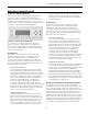
MUI Alarm History Reporting
If a fault occurs the fault will be recorded in history for
display on the medium user interface in the History Menu.
Each fault type will be displayed in the history menu with
a number between 0 and 3. A reading of 3+ will mean that
fault has occurred more than three times in the past. The
history menu can be cleared with a power cycle only. Alarm
date and time are not included in the history.
Inputs and Outputs Configuration
Field Selectable Options
Freeze Detection Limit Set Point (BI-5)
The freeze detection limit set point input allows you to
adjust the freeze detection limit set point (AI-5). When the
jumper is installed on BI-5 (Wire #24) the freeze detection
limit set point is factory set for 30°F [-1°C]. When the
jumper on BI-5 (Wire #24) is removed the freeze detection
set point will be 15°F [-9°C].
Accessory Outputs (BO-7 and BO-8)
Accessory Output 1 will be energized 90 seconds prior to
the compressor output being energized. Accessory Output
2 will be energized with the blower output (BO-1). When
the corresponding compressor output is turned off the
accessory output will be deactivated immediately. These
outputs are selectable for normally open or normally closed
operation through the Medium User interface or through the
Building Automation System.
Control Accessories
Zone Sensors
• TAXXJ02 Room Command Module
• TAXXA01 LCD Room Command Module
• A99 Sensor
MUI (LCD User interface) for diagnostics
and commissioning.
• MUIK3 - Panel Mount, Portable
• MUIK4 - Wall Mount
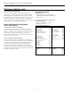
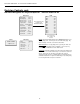
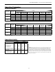
Envision Controls cont.
Input Name Input Output Name Output
Zone Temp 1 AI 1 Fan Enable BO1
Relative Humidity Input AI 2 Comp – Low Capacity BO2
Condensate Level AI 3 Reversing Valve BO3
Universal Temp Input AI 4 Comp – Full Capacity BO4
Water Coil Low Temperature Limit AI 5 Network Output/EH Output BO5
Warm/Cool Adjust and Temp Occ AI 6 Alarm BO6
Accessory 1 Output BO7
Occupied BI 1 Accessory 2 Output BO8
Emergency Shutdown BI 2 Network Controlled Output B09
Stage 1 Low Pressure BI 3
Network Viewable Input 1 BI 4 ECM2 Fan PWM1
Water Coil Low Temp Limit Set Point BI 5 Network Controlled Output PWM2
Network Viewable Input 2 BI 6
Thermostat Y1 BI 7
Thermostat Y2 BI 8
Thermostat O BI 9
Thermostat G B10
Stage 1 High Pressure BI11
Compressor Proving BI12
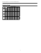
XP10 Expansion Card
Input Name Input Output Name Output
Unused AI 1 Unused BO 1
Unused AI 2 Unused BO 2
Unused AI 3 Unused BO 3
Unused AI 4 Unused BO 4
SINGLE and DUAL STAGE WATER-TO-AIR