Envision Console Installation Manual CONSOLE Geothermal/Water Source Heat Pumps • R-410A Refrigerant • 0.75-1.
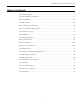
ENVISION CONSOLE INSTALLATION MANUAL Table of Contents Model Nomenclature . . . . . . . . . . . . . . . . . . . . . . . . . . . . . . . . . . . . . . . . . . . . . . . . . . . . . . . . . . . . . . 3 General Installation Information . . . . . . . . . . . . . . . . . . . . . . . . . . . . . . . . . . . . . . . . . . . . . . . . . . . . 4 Dimensional Data . . . . . . . . . . . . . . . . . . . . . . . . . . . . . . . . . . . . . . . . . . . . . . . . . . . . . . . . . . . . . . . 5-11 Installation Steps. . .
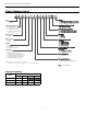
ENVISION CONSOLE INSTALLATION MANUAL Model Nomenclature 1-2 3 4-5 6 7 8 9 10 11 12 13 14 15-16 17 NC S 09 L 0 1 1 C N N B 5 SS C Vintage B – PSC Blower & Aluminum Air Coil C – ECM Blower & Aluminum Air Coil Model NC – Envision Series Console Non-Standard Option Details SS – Standard Option Cabinet Configuration C – Chassis Only W – Chassis with Cabinet S – Chassis Slope Top E – Chassis with Extended Slope Top Air Coil/Insulation Option 5 – AlumiSealTM/Extended Range 8 – No Co
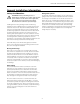
ENVISION CONSOLE INSTALLATION MANUAL General Installation Information Safety Considerations WARNING: Before performing service or maintenance operations on a system, turn off main power switches to the indoor unit. If applicable, turn off the accessory heater power switch. Electrical shock could cause personal injury. Installing and servicing heating and air conditioning equipment can be hazardous due to system pressure and electrical components.
ENVISION CONSOLE INSTALLATION MANUAL Dimensional Data - Flat Top Cabinet NCW09-18 @756B @3BC@< :34B @3BC@< B=> 4 2 3 / 0 5 / 0 47:B3@ 0@/193B 47:B3@ 0@/193B 1 8 6 7 23B/7: 0 23B/7: 0 4@=:/AB71 AB@7> 4@=; 0@=93< B/0 /<2 @3>:/13 =< 0@=93< 3253 =4 :35 /A A6=E< @3;=
ENVISION CONSOLE INSTALLATION MANUAL Dimensional Data - Slope Top Cabinet NCS09-18 @756B @3BC@< :34B @3BC@< B=> 4 2 3 0 5 / / 0 47:B3@ 0@/193B 47:B3@ 0@/193B 1 23B/7: / 23B/7: 0 8 BE7AB 3FB3<232 B/0 0/19 /<2 4=@B6 C:/AB71 AB@7> 4@=; 0@=93< B/0 /<2 @3>:/13 =< 0@=93< 3253 =4 :35 /A A6=E< @3;
ENVISION CONSOLE INSTALLATION MANUAL Dimensional Data - Extended Slope Top Cabinet NCE09-18 @756B @3BC@< B=> :34B @3BC@< 4 2 3 0 5 / 47:B3@ 0@/193B / 47:B3@ 0@/193B 1 0 8 7 6 23B/7: / BE7AB 3FB3<232 B/0 0/19 /<2 4=@B6 C:/AB71 AB@7> 4@=; 0@=93< B/0 /<2 @3>:/13 =< 0@=93< 3253 =4 :35 /A A
ENVISION CONSOLE INSTALLATION MANUAL Dimensional Data - Right Return Controls Detail 6/<2G 0=F 1=/<3: @3;=D3 4=@ /113AA B= 1=B7=B7=< AE7B16 3:31B@71 63/B ;=23 <=@;/: 0=7:3@:3AA AE7B16 =>B7=B7=3@ =< =44 AE7B16 1=<23@3AA=@ /113AA >/<3: @3;=D32 4=@ 1:/@7BG 0=B6 A723A =>B7=B7=:/B3 @3?C7@32 4=@ 2/;>3@ 7
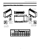
ENVISION CONSOLE INSTALLATION MANUAL Dimensional Data - Right Return Chassis Data = inches (cm) Models 09-12 Models 15-18 37.88 (96.2) 9.38 (23.8) CONTROL PANEL 42.88 (108.9) 8.88 (22.6) 28.5 (72.4) CONTROL PANEL 34.0 (86.4) 1.5 (3.8) 1.5 (3.8) BLOWER ACCESS PANEL BLOWER ACCESS PANEL COMPRESSOR ACCESS PANEL COMPRESSOR ACCESS PANEL 1.5 (3.8) 1.5 (3.8) 4.37 (11.1) 4.32 (11.0) FILTER FILTER 10.31 (26.2) 4.5 (11.4) WATER OUT 1/2˝ FPT WATER IN 1/2˝ FPT 11.75 (29.8) 4.5 (11.
ENVISION CONSOLE INSTALLATION MANUAL Dimensional Data - Left Return Controls Detail 1=/<3: @3;=D3 4=@ /113AA B= 1=3@ =< =44 AE7B16 :=E D=:B/53 B3@;7B7=B7=B7=B7=B7=< AE7B16 =>B7=@3AA=@ /113AA >/<3: @3;=D32 4=@ 1:/@7BG 0=B6 A723A =>B7=B7=
ENVISION CONSOLE INSTALLATION MANUAL Dimensional Data - Left Return Chassis Data = inches (cm) Models 09-12 28.5 (72.4) Models 15-18 37.88 (96.2) 9.38 (23.8) 34.0 (86.4) CONTROL PANEL 42.88 (108.9) 8.88 (22.6) CONTROL PANEL 1.50 (3.8) 1.50 (3.8) 1.50 (3.8) 1.50 (3.8) BLOWER ACCESS PANEL BLOWER ACCESS PANEL COMPRESSOR ACCESS PANEL COMPRESSOR ACCESS PANEL 4.37 (11.1) 4.32 (11.0) FILTER FILTER 10.31 (26.2) 4.5 (11.4) WATER OUT 1/2˝ FPT WATER IN 1/2˝ FPT 11.75 (26.
ENVISION CONSOLE INSTALLATION MANUAL Installation Steps Step 1: Unpack Equipment and Inspect for Damage Step 2: Determine Equipment Location • • • • • Choose level flooring surface (Correctable with shims. Do not pitch towards drain.) Location of wall support and fasteners required to secure chassis backplate. Easy access for both installation and service. Consider availability and ease of wiring, water piping and condensate drain. No obstructions to block airflow in front of the unit.
ENVISION CONSOLE INSTALLATION MANUAL Installation Steps cont. Step 4: Provide Water and Condensate Drain Connections • A two-pipe reverse return piping configuration is recommended as it equalizes the piping circuit lengths and delivers even water flow to each unit. A direct return piping configuration may be used, but it may be difficult to achieve and maintain proper water flow to the units. • An air vent must be installed in the water distribution system.
ENVISION CONSOLE INSTALLATION MANUAL Installation Steps cont. Step 5: Provide Line Voltage Wiring • Check unit data plate located on control side of chassis for ampacity and fuse size. • Remove electrical knockouts from chassis backplate. • Run line voltage wiring through knockout and secure wiring to backplate or disconnect. Step 6: Chassis Installation • Level and secure backplate to wall. • Position the chassis against back plate.
ENVISION CONSOLE INSTALLATION MANUAL Installation Steps cont. Field Converting Console Chassis is normally configured with controls on right end and piping on left end (see Figure 3 top view). In this position panel number 1 would be positioned against wall or back plate. Unit may also be turned 180° against wall or back plate. In this position controls will be on left end and piping on right end panel number 2 would be positioned against wall or back plate.
ENVISION CONSOLE INSTALLATION MANUAL System Cleaning and Flushing Cleaning and Flushing Prior to start up of any heat pump, the water circulating system must be cleaned and flushed of all dirt and debris. If the system is equipped with water shutoff valves, the supply and return runouts must be connected together at each unit location (This will prevent the introduction of dirt into the unit, see Figure 7). The system should be filled at the water make-up connection with all air vents open.
ENVISION CONSOLE INSTALLATION MANUAL Open Loop Ground Water Systems Always maintain water pressure in the heat exchanger by placing water control valves at the outlet of the unit to prevent mineral precipitation. Use a closed, bladder-type expansion tank to minimize mineral formation due to air exposure. Insure proper water flow through the unit by checking pressure drop across the heat exchanger and comparing it to the figures in unit capacity data tables in the specification catalog. 1.
ENVISION CONSOLE INSTALLATION MANUAL Electrical Connections General Be sure the available power is the same voltage and phase as that shown on the unit serial plate. Line and low voltage wiring must be done in accordance with local codes or the National Electric Code, whichever is applicable. 208 Volt Operation All Envision Series 208/230 units are factory wired for 230 volt operation. For 208 volt operation, the red and blue transformer wires must be switched.
ENVISION CONSOLE INSTALLATION MANUAL Electrical Data ECM Motor Compressor LRA Fan Motor FLA Total Unit FLA Min Circ Amp 8.0 50.0 4.25 12.3 14.3 20 4.1 21.0 2.6 6.7 7.7 10/15 6.8 7.9 10/15 13.8 16.1 25 8.8 10/15 10/15 Model Rated Voltage Voltage Min/Max MCC RLA 115/60/1 104/127 12.5 09 208-230/60/1 187/253 6.4 265/60/1 238/292 6.7 4.3 22.0 2.5 115/60/1 104/127 14.8 9.5 50.0 4.25 208-230/60/1 187/253 7.7 4.9 25.0 2.6 7.
ENVISION CONSOLE INSTALLATION MANUAL Auxiliary Heat Ratings ECM Motors Model 09-12 (1 kW) 09-12 (2 kW) 15-18 (3 kW) Rated Voltage Voltage Min./Max. Heater Element Watts Fan Motor FLA Heater Element FLA Total Unit FLA Min. Circuit Amp. Max. Fuse/ Brkr. 10 208/60/1 197/254 818 2.45 3.93 6.4 8.0 230/60/1 197/254 1000 2.60 4.35 7.0 8.7 15 265/60/1 239/291 1000 2.50 3.77 6.3 7.8 10 20 208/60/1 197/254 1636 2.45 7.86 10.3 12.9 230/60/1 197/254 2000 2.60 8.70 11.
ENVISION CONSOLE INSTALLATION MANUAL Wiring Schematics CCM - ELECTRONIC THERMOSTAT 208-230-265/60/1 Compressor S Blue PSC Fan Motor C Brn Grn Red Wht Unit Power Supply 208-230/60/1 or 265-277/60/1 Ground Lug R Handi - Box Blk G Tan (33) Cap White (28) L T2 T1 CC L2 L1 H Brown (26) Black (31) White (28) Red (32) Black(29) Black Red (30) High 4 Black (25) 2 NOTE 1 Blue 230V 265V Black (27) Red 208V Transformer Low RB 5 Brown (26) Red (19) 24V PB 1 Yellow Black/White 2
ENVISION CONSOLE INSTALLATION MANUAL Wiring Schematics, cont.
ENVISION CONSOLE INSTALLATION MANUAL Wiring Schematics cont.
ENVISION CONSOLE INSTALLATION MANUAL Wiring Schematics cont.
ENVISION CONSOLE INSTALLATION MANUAL Wiring Schematics cont.
ENVISION CONSOLE INSTALLATION MANUAL Wiring Schematics cont.
ENVISION CONSOLE INSTALLATION MANUAL Envision Console Controls Control General Description CCM Control The CCM (Compressor control module) is a more reliable replacement for electro-mechanical control applications. It features a small microprocessor board that handles the lockout function of the unit. A second microporcessor handles the unit mounted thermostat for maintaining accurate room temperature. Residential and commercial applications requiring minimal but reliable controls.
ENVISION CONSOLE INSTALLATION MANUAL Envision Console Controls cont. The user selects either “Heat/Cool” or “Fan Only” on the mode switch, then either “High” or “Low” at the fan speed switch. The temperature can be controlled by rotating the thermostat control knob. Figure 6: Unit Mounted Control Optional Versatec Microprocessor Control Features The Versatec microprocessor board provides control of the entire unit as well as outputs for status modes, faults and diagnostics.
ENVISION CONSOLE INSTALLATION MANUAL Envision Console Controls cont. prevent loss of refrigerant charge and a low suction temperature thermistor for freeze sensing. Upon a continuous 30-second measurement of the fault (immediate for high pressure), compressor operation is stopped.
ENVISION CONSOLE INSTALLATION MANUAL Envision Console Controls cont. Optional FX10 Control Random Start A delay of 1 to 120 seconds is generated after each powerup to prevent simultaneous startup of all units within a building after the release from an unoccupied cycle or power loss. Emergency Shutdown A field-applied dry contact can be used to place the control into emergency shutdown mode. During this mode, all outputs on the board are disabled.
ENVISION CONSOLE INSTALLATION MANUAL Envision Console Controls cont. Control Timing & Fault Recognition Delays Lead compressor “ON” delay ..........................................90 seconds (not applicable for single compressor models) Minimum compressor “ON” time ...................................... 2 minutes (except for fault condition) Short cycle delay ..................................................................... 5 minutes Random start delay ..................................................
ENVISION CONSOLE INSTALLATION MANUAL Envision Console Controls cont. Control and Safety Feature Details Emergency Shutdown The emergency shutdown mode can be activated by a command from a facility management system or a closed contact on BI-2. The default state for the emergency shutdown data point is off. When the emergency shutdown mode is activated, all outputs will be turned off immediately and will remain off until the emergency shutdown mode is de-activated.
ENVISION CONSOLE INSTALLATION MANUAL Envision Console Controls cont. enabled. During the heating cycle the reversing valve will be commanded into the off position. mode. The delay should not be less than 1 second and not longer than 120 seconds. If the control is in test mode the random start delay will be shortened to 5 seconds.
ENVISION CONSOLE INSTALLATION MANUAL Envision Console Controls cont. Inputs and Outputs Configuration Field Selectable Options Freeze Detection Limit Set Point (BI-5) The freeze detection limit set point input allows you to adjust the freeze detection limit set point (AI-5). When the jumper is installed on BI-5 (Wire #24) the freeze detection limit set point is factory set for 30°F. When the jumper on BI-5 (Wire #24) is removed the freeze detection limit set point will be 15°F.
ENVISION CONSOLE INSTALLATION MANUAL Envision Console Controls cont.
ENVISION CONSOLE INSTALLATION MANUAL Envision Console Controls cont. MUI Menu Navigation for Single Compressor - Envision Water-to-Air ECM Maintenance MinClgSetpt 60.0 ºF SW1 MaxHtgSetpt 89.9 ºF SW2 OFF W Coil LoLim1 30.0 ºF SW3 ON W Coil LoLim2 15.
ENVISION CONSOLE INSTALLATION MANUAL Unit Startup Notes Emergency Electric Resistance Heat A factory-installed emergency electric heater package is available. Rated for 2,000 watts on models NC09 through NC12 and 3,000 watts on models NC15 through NC18. The heater package consists of ni-cad elements, ceramic insulators, and thermal limit switches. A concealed, chassis mounted rocker switch controls the heater mode operation and allows the field installation of an aquastat for boilerless unit operation.
ENVISION CONSOLE INSTALLATION MANUAL Unit Startup Checklist / Unit Startup Steps Before Powering Unit, Check The Following: • • • • • • • • • • • • • • High voltage is correct and matches nameplate. Fuses, breakers and wire size correct. Low voltage wiring complete. Piping completed and water system cleaned and flushed. Air is purged from closed loop system. Isolation valves are open, water control valves or loop pumps wired. Condensate line open and correctly pitched.
ENVISION CONSOLE INSTALLATION MANUAL Unit Operating Parameters Single Speed Models Cooling Entering Water Temp °F Water Flow GPM/Ton Suction Pressure PSIG Discharge Pressure PSIG 09-18 Superheat 09-18 Subcooling Water Temp Rise °F Air Temp Drop °F DB 1.5 127 - 144 205 - 225 5 - 10 10 - 14 18 - 22 18 - 22 3.0 120 - 140 185 - 205 7 - 15 5 - 10 8 - 10 18 - 22 1.5 139 - 154 280 - 300 8 - 11 8 -12 18 - 22 18 - 22 3.0 137 - 152 250 - 270 9 - 12 7 - 11 8 - 10 18 - 22 1.
ENVISION CONSOLE INSTALLATION MANUAL DEALER: PHONE #: DATE: PROBLEM: MODEL #: Startup/Troubleshooting Form SERIAL #: COOLING CYCLE ANALYSIS PSI = SAT °F °F Unit Amp Draw: °F AIR COIL Loop: Open Closed Line Voltage: °F SUCTION COMPRESSOR REVERSING VALVE COAX EXPANSION VALVE SOURCE DISCHARGE °F °F LIQUID LINE SAT °F PSI = °F °F PSI PSI Superheat BRINE IN Subcooling BRINE OUT Heat of Extraction/Rejection = GPM x 500 (485 for water/antifreeze) x ∆T Note: DO NOT hook up pressure ga
ENVISION CONSOLE INSTALLATION MANUAL Pressure Drop Pressure Drop (psi) Model GPM 1.2 09 12 15 18 30°F 50°F 70°F 90°F 110°F 1.0 0.9 0.8 0.7 0.6 1.8 2.3 2.2 2.0 1.9 1.8 2.5 3.8 3.7 3.5 3.3 3.1 1.5 0.9 0.8 0.7 0.6 0.5 2.3 1.7 1.5 1.4 1.3 1.1 3.5 3.0 2.7 2.5 2.4 2.2 2.0 1.7 1.6 1.5 1.4 1.3 3.0 3.3 3.2 3.0 2.9 2.8 4.5 5.7 5.5 5.3 5.1 4.9 3.0 1.7 1.6 1.5 1.4 1.3 4.0 4.1 4.0 3.9 3.7 3.6 5.5 7.9 7.6 7.4 7.2 6.
ENVISION CONSOLE INSTALLATION MANUAL Preventive Maintenance Water Coil Maintenance Condensate Drain 1. Keep all air out of the water. An open loop system should be checked to ensure that the well head is not allowing air to infiltrate the water line. Lines should always be airtight. 2. Keep the system under pressure at all times. It is recommended in open loop systems that the water control valve be placed in the discharge line to prevent loss of pressure during off cycles.
ENVISION CONSOLE INSTALLATION MANUAL Notes 43
ENVISION CONSOLE INSTALLATION MANUAL Revision Guide Pages: Date: By: All Updated With Aluminum Air Coils Description: 02 Mar 2014 DS 44 Added Revision Guide 02 Mar 2014 DS 44
Manufactured by WaterFurnace International, Inc. 9000 Conservation Way Fort Wayne, IN 46809 www.waterfurnace.com IM1010CNA 03/14 Product: Type: Size: Document: Envision Series Console Geothermal/Water Source Heat Pumps 0.75-1.5 Ton Installation Manual ©2014 WaterFurnace International, Inc., 9000 Conservation Way, Fort Wayne, IN 46809-9794. WaterFurnace has a policy of continual product research and development and reserves the right to change design and specifications without notice.