NXW Reversible Chiller Installation Manual NXW 10 to 50 Tons Commercial Reversible Chiller - 60 Hz Installation Information Water Piping Connections Electrical Data Microprocessor Control Startup Procedures Preventive Maintenance IM2502WN 06/14
NXW REVERSIBLE CHILLER INSTALLATION MANUAL Table of Contents Model Nomenclature . . . . . . . . . . . . . . . . . . . . . . . . . . . . . . . . . . . . . . . . . . . . . . . . . . . . . . . . . . . . . . 4 General Installation Information . . . . . . . . . . . . . . . . . . . . . . . . . . . . . . . . . . . . . . . . . . . . . . . . . . 5-6 Physical Dimensions . . . . . . . . . . . . . . . . . . . . . . . . . . . . . . . . . . . . . . . . . . . . . . . . . . . . . . . . . . . . . 7-8 Physical Data . . . .
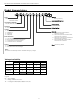
ENVISION2 NXW REVERSIBLE CHILLER INSTALLATION MANUAL Model Nomenclature 1-3 4-6 7 8 9 10 11 12 13 14-15 16 NXW 120 R 3 A E 8 N N SS * Vintage * - Factory Use Only Model NXW – Envision2 Series Reversible Chiller Non-Standard Options SS - Standard Unit Capacity (MBTUH) 120, 180, 240, 360, 600 Future Option N – Future Use Operation R - Reversible Future Option N – Future Use Voltage 3 – 208-230/60/3 4 – 460/60/3 5 – 575/60/3 8 – 380/60/3 Controls 8 – FX10 without Communication, wi
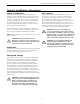
ENVISION2 NXW REVERSIBLE CHILLER INSTALLATION MANUAL General Installation Information Safety Considerations Unit Location Installing and servicing air conditioning and heating equipment can be hazardous due to system pressure and electrical components. Only trained and qualified service personnel should install, repair or service heating and air conditioning equipment.
ENVISION2 NXW REVERSIBLE CHILLER INSTALLATION MANUAL General Installation Information cont. Mounting Units Remove the unit from the wooden shipping skids (see physical dimensions). Units will be shipped with heavy duty rubber grommets to reduce sound that can be transmitted through the floor via the frame (see isolator drawing). For additional sound attenuation, use heavy duty spring isolation that can reduce sound levels by 3 dBA (see springs drawing).
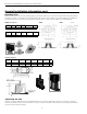
ENVISION2 NXW REVERSIBLE CHILLER INSTALLATION MANUAL Physical Dimensions EMERGENCY STOP SWITCH DISCONNECT SWITCH CONTROL BOX COVER SERVICE PORTS MAIN POWER CONNECTION SOURCE WATER OUT SOURCE WATER IN FX-10 CONTROLLER DISPLAY LOAD WATER IN ACCESS DOOR LOAD WATER OUT SIDE ACCESS PANEL DOORS VIBRATION PADS NOTES: 1. DO NOT SCALE DRAWING. FRONT TOP 2.40 TO PORT (SERVICE) SIDE "B" REAR J SOURCE WATER OUT "G" SOURCE WATER IN "A" "F" LOAD WATER IN 7.50 4.50 4.00 7.00 "E" LOAD WATER OUT 4.
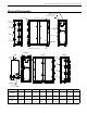
ENVISION2 NXW REVERSIBLE CHILLER INSTALLATION MANUAL Physical Dimensions, cont. T R S T DETAIL A P 25.00 N M 24.00 A K 52.00 L 24.00 SHADED AREAS REPRESENT REQUIRED CLEARANCE FOR SERVICE & MAINTENANCE OF EQUIPMENT. Model K L M N P R S T* 120-180 57.0 [1448] 42.0 [1067] 63.1 [1603] 15.9 [404] 19.5 [495] 9.7 [246] 1.3 [33] 2.0 [50.8] 240-360 65.0 [1651] 42.0 [1067] 69.9 [1775] 19.9 [505] 19.5 [495] 9.7 [246] 1.8 [46] 2.0 [50.8] 600 70.0 [1778] 42.0 [1067] 76.
ENVISION2 NXW REVERSIBLE CHILLER INSTALLATION MANUAL Physical Data Model 120 180 240 360 600 Compressor Total Weight Refrigerant Charge* Shipping Installed 5.3 720 710 [2.4] [327] [323] 7.8 838 844 [3.5] [381] [384] 10.5 1130 1152 [4.8] [514] [524] 17.9 1320 1388 [8.1] [600] [631] 27.3 1748 1850 [12.
ENVISION2 NXW REVERSIBLE CHILLER INSTALLATION MANUAL Field Connected Water Piping NOTE: The placement and connection of the water circulating pump(s) must be taken into consideration prior to designing the final water piping systems. General System piping should be kept as simple as possible to minimize the pressure drop, but hand valves should be field installed to facilitate unit servicing.
ENVISION2 NXW REVERSIBLE CHILLER INSTALLATION MANUAL Envision2 NXW Typical Piping Standard Piping Factory Installed Field Supplied and Installed Pump Isolation Valves From Load Water Temperature Sensors Brazed Plate Heat Exchanger 1/4” NPT Pressure/Temperature Port Strainer FS To Load Isolation Valve Note: System piping should have drain ports to enable flushing and cleaning of heat exchangers. On systems utilizing pumps with VFDs, an automatic flow control valve must be installed.
ENVISION2 NXW REVERSIBLE CHILLER INSTALLATION MANUAL Envision2 NXW Application Data 1.0. Minimum Fluid Volume 1.4. Flow Sensing Devices A. A. B. Water-to-water heat pumps require a minimum amount of source and load side fluid volume to ensure accurate and stable temperatures during system operation. For normal air conditioning type applications, it is recommended to use at least 7 gallons/ton.
ENVISION2 NXW REVERSIBLE CHILLER INSTALLATION MANUAL Envision2 NXW Application Data cont. 1.6. Insulation 1.7. Brine Applications A. A. Heat pumps are built with factory installed insulation on any surface that may be subject to temperatures below the room dew point. Surface Condensation Chart B.
ENVISION2 NXW REVERSIBLE CHILLER INSTALLATION MANUAL System Cleaning and Flushing Cleaning and Flushing Refill the system with clean water. Test the system water for acidity and treat as required to leave the water slightly alkaline (pH 7.5 to 8.5). The specified percentage of antifreeze may also be added at this time. Use commercial grade antifreeze designed for HVAC systems only. Environol™ brand antifreeze is recommended.
ENVISION2 NXW REVERSIBLE CHILLER INSTALLATION MANUAL Electrical Data Model Rated Voltage Compressor1 Voltage Min/Max MCC RLA LRA Total Unit FLA Min Circ Amp Min Fuse/ HACR Max Fuse/ HACR2 208-230/60/3 187/253 36.0 23.1 160.0 46.2 52.0 60.0 70 460/60/3 414/506 19.0 12.2 87.0 24.4 27.5 30.0 35 575/60/3 517/633 13.5 8.7 62.0 17.4 19.6 20.0 25 380/60/3 342/418 19.0 12.2 95.0 24.4 27.5 30.0 35 208-230/60/3 187/253 45.0 28.8 235.0 57.6 64.8 70.
ENVISION2 NXW REVERSIBLE CHILLER INSTALLATION MANUAL Electrical Data cont.
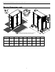
F8 EST LST ELT LLT L-WCT Circuit 2 S-WCT Circuit 2 L-WCT Circuit 1 S-WCT Circuit 1 T T T T T T T T L2 L2 White(H) NOTE 7 L1 F7 L1 Black(G) L1 2 HP-2 HP-1 LP-2 LP-1 RV1 RV2 L3 F9 L3 Red(J) L2 F2 L2 L3 F6 L3 Red(C) Brn/Wht (86) Blue/Wht (49B) Black (73A) Black (74A) Black/Org (73B) Black/Org (74B) Brn/Blk (42) Brn/Blk (41) Brn/Wht (87) Blue (76A) Blue (49A) Blue/Wht (76B) Tan/Black (85) Tan/White (82) Tan/White (83) Tan/Black (84) White/Blue (33) White/Blue (34
L1 F8 EST LST ELT LLT L-WCT Circuit 2 S-WCT Circuit 2 L-WCT Circuit 1 S-WCT Circuit 1 T T T T T T T T L2 L2 White(H) NOTE 7 L1 F7 L1 Black(G) Unit Power Supply F1 L1 HP-2 HP-1 LP-2 LP-1 RV1 RV2 L3 F9 L3 Red(J) L2 F2 L2 D01 L3 F6 L3 Red(C) Brn/Wht (86) Blue/Wht (49B) Black (73A) Black (74A) Black/Org (73B) Black/Org (74B) Brn/Blk (42) Brn/Blk (41) Brn/Wht (87) Blue (76A) Blue (49A) Blue/Wht (76B) Tan/Black (85) Tan/White (82) Tan/White (83) Tan/Black (84) W
ENVISION2 NXW REVERSIBLE CHILLER INSTALLATION MANUAL Field Wiring and Control Setup High Voltage Connections Line Voltage Power supply wiring connects directly to lugs on the topo of the electrical disconnect. In 208-230V applications, heat pumps are factory wired for 208V supply. In the case of 230V supply, the blue and red wires from the primary of the transformer will need to be swapped.
ENVISION2 NXW REVERSIBLE CHILLER INSTALLATION MANUAL Field Wiring and Control Setup cont. Accessory Relay Setup °F or °C - Unit of Measure The accessory output set to “close” upon Y1 compressor call (compressor is delayed 90 sec. after Y1) but can be set to “open” with Y1.
ENVISION2 NXW REVERSIBLE CHILLER INSTALLATION MANUAL Control Features Advanced Freeze Detection Operation: “Pre Freeze” Alarm Advanced Freeze Detection System The source and load heat exchangers are protected by a multi-sourced temperature logic strategy. The temperature logic is based upon the refrigerant temperature sensed as the refrigerant is about to enter the heat exchanger; while entering and leaving water temperatures are being used as correlating factors.
ENVISION2 NXW REVERSIBLE CHILLER INSTALLATION MANUAL Control Features cont. minimum on time does not apply if the high-pressure switch trips. The compressor will not restart until the short cycle time delay has been satisfied. If the high-pressure fault occurs in one circuit the other compressor will continue to operate based on the heating or cooling demand.
ENVISION2 NXW REVERSIBLE CHILLER INSTALLATION MANUAL Control Features cont. • When the controlling temperature sensor is set to select the Load LW Temp, the setpoint control will operate strictly in a proportional mode with offsets and differentials used to determine the appropriate capacity to use. In this mode, the following parameters are used: • Stage Delay (30) • Gain (2) • PIDY1 Ref (7.
ENVISION2 NXW REVERSIBLE CHILLER INSTALLATION MANUAL Sequence of Operation Power Fail Restart Compressor Lead/Lag When the controller is first powered up, the outputs will be disabled for a random start delay. The delay is provided to prevent simultaneous starting of multiple heat pumps. Once the timer expires, the controller will operate normally. Compressor lead/lag is a standard part of the FX10 control system. The unit is shipped from the factory with lead/ lag enabled.
ENVISION2 NXW REVERSIBLE CHILLER INSTALLATION MANUAL Inputs and Outputs Configuration DUAL STAGE WW Input Name Entering Load Water Temperature Leaving Load Water Temperature 1 Source Heating Freeze Detection 1 Source Heating Freeze Detection 2 Load Cooling Freeze Detection 1 Load Cooling Freeze Detection 2 Input AI 1 AI 2 AI 3 AI 4 AI 5 AI 6 Load Flow Proving Switch Emergency Shutdown Stage 2 Low Pressure Source Htg Freeze Detection Select - 30ºF Load Htg Freeze Detection Select - 30ºF Stage 1 Low Pressur
ENVISION2 NXW REVERSIBLE CHILLER INSTALLATION MANUAL Unit Display and Interface Cont. MUI Menu Navigation Welcome Info Temp Info Dual Stage Setpt Reversible Chiller PRODCWWE-10 MM/DD/YY Stat Temp Temperatures Enter Load 77.2 ºF Leave Load 51.0 ºF Enter Source 70.0°F Leave Source 66.0°F Source Frz 1 77.8°F Source Frz 2 30.0°F Load Frz 1 30.0°F Load Frz 2 30.0°F Src Frz Setpt 30.0°F LD Frz Setpt 30.
ENVISION2 NXW REVERSIBLE CHILLER INSTALLATION MANUAL Unit Display and Interface cont. Menu and Menu Contents Source Flow – Source Flow Switch is Not Closed Alarm • The source flow switch must be closed prior to either compressor starting and must remain closed for the entire run-time of the compressor(s). • Displays unit alarms until the unit has been reset (Unit alarms can be reset by holding both the Escape (ESC) key and Return (←) key for five seconds or by power cycling the unit.
ENVISION2 NXW REVERSIBLE CHILLER INSTALLATION MANUAL Reference Calculations Heating Calculations: LWT = EWT - HE GPM x 500* Cooling Calculations: LWT = EWT + HR GPM x 500* NOTE: * When using water. Use 485 for 15% methanol/water or Environol solution.
ENVISION2 NXW REVERSIBLE CHILLER INSTALLATION MANUAL Operating Parameters Heating Mode Entering Load Temp (oF) 60 80 100 120 Entering Source Temp (oF) Suction Pressure (psig) Discharge Pressure (psig) Superheat (oF) Subcooling (oF) 30 75-100 200-215 10-12 10-13 50 100-125 200-215 12-14 8-12 70 125-150 215-230 14-18 8-12 90 150-165 230-255 25-30 8-12 30 75-100 285-300 10-12 10-13 50 100-125 300-315 12-14 8-12 70 125-150 315-330 14-18 8-12 90 150-165 330-345 25
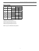
ENVISION2 NXW REVERSIBLE CHILLER INSTALLATION MANUAL Pressure Drop Pressure Drop (psi) Model 120 180 240 360 600 GPM 30°F 50°F 70°F 90°F 110°F 20 0.8 0.7 0.6 0.6 0.5 30 2.1 1.9 1.8 1.7 1.5 40 3.3 3.1 2.9 2.8 2.5 30 0.9 0.8 0.7 0.7 0.6 45 2.3 2.2 2.0 2.0 1.8 60 3.7 3.5 3.3 3.2 2.9 40 1.3 1.2 1.1 1.1 1.0 60 3.2 3.0 2.9 2.8 2.6 80 5.0 4.7 4.6 4.4 4.2 60 1.3 1.2 1.1 1.0 0.9 90 3.1 2.9 2.8 2.7 2.4 120 4.8 4.6 4.4 4.3 3.9 100 2.
ENVISION2 NXW REVERSIBLE CHILLER INSTALLATION MANUAL Compressor Resistance Model 208-230 380 460 575 120 .539 / .528 /.528 .575 / .575 / .575 2.116 / 2.088 / 2.072 3.333 / 3.289 / 3.263 180 .32 / .32 / .33 N/A 1.29 / 1.28 / 1.33 1.99 / 1.96 / 2.05 240 .33 / .33 / .33 N/A 1.13 / 1.11 / 1.10 1.73 / 1.66 / 1.75 360 .20 / .20 / .20 0.57 / 0.57 / 0.57 .83 / .83 / .83 1.32 / 1.32 / 1.32 600 N/A .36 / .36 / .36 0.52 / .52 / .52 .82 / .82 / .
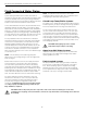
ENVISION2 NXW REVERSIBLE CHILLER INSTALLATION MANUAL Troubleshooting Should a major problem develop, refer to the following information for possible causes and corrective steps. If compressor won’t run: 1. 2. 3. 4. 5. 6. 7. 8. 9. The fuse may be open or the circuit breaker is tripped. Check electrical circuits and motor windings for shorts or grounds. Investigate for possible overloading. Replace fuse or reset circuit breakers after fault is corrected. Supply voltage may be too low.
ENVISION2 NXW REVERSIBLE CHILLER INSTALLATION MANUAL Heating Cycle Analysis ______PSI = ______SAT°F ______°F Braze Plate Suction RV Compressor Discharge ______°F Liquid Line FD ______PSI = ______SAT°F Braze Plate ______°F Unit Amp Draw ____________ Entering Source Water ________°F Line Voltage _________ Entering Water Pressure Drop _____ PSI Loop:______ Open ______ Closed Leaving Source Water ________°F Subcooling _______ Leaving Water Pressure Drop _____ PSI Superheat _______ NOTE: Do not
ENVISION2 NXW REVERSIBLE CHILLER INSTALLATION MANUAL Envision NXW Troubleshooting Form Company Name: _________________________________ Technician Name: ________________________________ Model No: ______________________________________ Owner’s Name: __________________________________ Installation Address: ______________________________ Company Phone No: ______________________________ Date: __________________________________________ Serial No:_______________________________________ Open or Closed Loop: _____
ENVISION2 NXW REVERSIBLE CHILLER INSTALLATION MANUAL NXW Startup Job Site Recording Process 1. Complete the top of the NXW Start-Up Form for each unit. *Be sure to note the mode (Heat/Cool) you will be testing the unit in as well as freeze protection details of type and concentration (Test to Verify). If starting-up in both heating and cooling modes, a start-up form for each mode will need to be completed. *The unit must be tested in both heating and cooling modes. 2.
ENVISION2 NXW REVERSIBLE CHILLER INSTALLATION MANUAL NXW Pre-Start-Up Checklist CHILLER PRE-START-UP CHECKLIST Project Name: Address: City/State/Zip: WaterFurnace Order #: Date: Mechanical Contractor: Contact Name: Telephone: Purchase Order #: Prior to starting the chiller(s), the mechanical contractor is responsible for reviewing all of the installation and operational information supplied by the manufacturer to ensure that the system is ready to be started.
ENVISION2 NXW REVERSIBLE CHILLER INSTALLATION MANUAL NXW Start-Up Form Start-up Date Unit Model # Unit Tag # Unit Serial # Size: Start-up Company Start-Up Mode Employee Name Cooling / Heating Job Name Voltage across L1-L2 Voltage across L2-L3 Water Side Balance Complete Voltage across L1-L3 YES / NO Electrical Data Circuit 1 Circuit 2 Compressor Amps (Red Wire) 208 Compressor Amps (Black Wire) 380 Circuit 1 Circuit 2 Entering Load Water Temperature with no Compressors running Leaving L
ENVISION2 NXW REVERSIBLE CHILLER INSTALLATION MANUAL Preventive Maintenance Unit Heat Exchanger Maintenance Replacement Procedures 1. 2. When contacting the company for service or replacement parts, refer to the model number and serial number of the unit as stamped on the serial plate attached to the unit.
ENVISION2 NXW REVERSIBLE CHILLER INSTALLATION MANUAL Service Parts List 120 Part Description Switches / Sensors Refrigeration Components Compressor 380/60/3 460/60/3 575/60/3 208-230/60/3 460/60/3 575/60/3 34P658-06 34P658-03 34P658-04 34P658-05 34P617-03 34P617-04 34P617-05 Compressor Sound Jacket 92P519-04 92P519-03 Thermal Expansion Valve 33P620-05 33P620-04 Filter Dryer 1 1 Reversing Valve with Coil 33P526-05 33P077-06 Vibration Absorber (suction) 32P508-06 32P508-05 Vi
ENVISION2 NXW REVERSIBLE CHILLER INSTALLATION MANUAL Service Parts List, cont.
ENVISION2 NXW REVERSIBLE CHILLER INSTALLATION MANUAL Service Parts List, cont.
ENVISION2 NXW REVERSIBLE CHILLER INSTALLATION MANUAL Revision Guide Pages: All Description: First Published 42 Date: By: 02 Jun 2014 DS
Manufactured by WaterFurnace International, Inc. 9000 Conservation Way Fort Wayne, IN 46809 www.waterfurnace.com IM2502WN 06/14 Product: Type: Size: Document: Envision2 NXW Reversible Chiller - 60 Hz 10-50 Tons Installation Manual ©2014 WaterFurnace International, Inc., 9000 Conservation Way, Fort Wayne, IN 46809-9794. WaterFurnace has a policy of continual product research and development and reserves the right to change design and specifications without notice.