Versatec Base 50 Hz Series Installation Manual Commercial 005-017kW Geothermal/Water Source Heat Pump 50Hz Installation Information Water Piping Connections Electrical Startup Procedures Troubleshooting Preventive Maintenance IM1251AUB 01/15
VERSATEC BASE SERIES INSTALLATION MANUAL Table of Contents Model Nomenclature . . . . . . . . . . . . . . . . . . . . . . . . . . . . . . . . . . . . . . . . . . . . . . . . . . . . . . . . . . . . . . 4 General Installation Information . . . . . . . . . . . . . . . . . . . . . . . . . . . . . . . . . . . . . . . . . . . . . . . . . . . . 5 Dimensional Data . . . . . . . . . . . . . . . . . . . . . . . . . . . . . . . . . . . . . . . . . . . . . . . . . . . . . . . . . . . . . . .
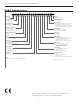
VERSATEC BASE 50Hz SERIES INSTALLATION MANUAL Model Nomenclature 1-3 4 5-7 8 9 10 11 12 13 14 15 16 17 18 19 20 UBK V 010 T L 7 0 1 C A N A N 0 A 3 21 22-23 24 0 SS * Model Type UBK – Versatec Base Vintage * - Factory Use Only Cabinet Configuration V – Vertical H - Horizontal Non-Standard Options SS – Standard Drain Pan Option 0 – Composite, No Secondary Connection 1 – Composite, Secondary Connection 2 – Stainless Steel, No Secondary Connection 3 – Stainless Steel, Sec
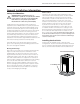
VERSATEC BASE SERIES 50Hz INSTALLATION MANUAL General Installation Information Unit Location Safety Considerations Locate the unit in an indoor area that allows for easy removal of the filter and access panels. Location should have enough space for service personnel to perform maintenance or repair. Provide sufficient room to make water, electrical and duct connection(s).
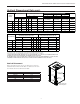
VERSATEC BASE 50Hz SERIES INSTALLATION MANUAL Vertical Dimensional Data Standard filter rails for open return applications Field installed duct flange Deluxe filter rack for ductable return applications A A N S R Air coil N Q P B AIR COIL SIDE AIR COIL SIDE Q P FRONT ACCESS PANEL B 2' (61 cm) Alternate Service Access FRONT F M F M Top View - Right Return Top View - Left Return 2' (61 cm) Service Access Left Return (Right Return Opposite Side) Isometric View - Left Return T U W
VERSATEC BASE SERIES 50Hz INSTALLATION MANUAL Vertical Dimensional Data cont. Overall Cabinet Vertical Models A B Width Depth 005 C Water Connections 1 2 5 D E H Electrical Knockouts 7 K 6 J Loop 8 L 1/2” (1.27cm) cond 1” (2.54cm) cond 1” (2.54cm) cond Height* In Out Condensate Water FPT M Low Voltage Low Voltage Power Supply Filter Rack Width cm. 57.2 56.4 76.7 6.6 19.3 27.4 19.1 mm 23.9 13.7 18.8 5.6 006-007 cm. 57.2 56.4 91.9 6.6 19.3 27.4 19.1 mm 23.9 13.
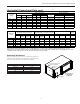
VERSATEC BASE 50Hz SERIES INSTALLATION MANUAL Horizontal Dimensional Data 5.3 cm Standard filter rails 5.3 cm Standard filter rails 2.5 cm knockout 1.3 cm knockout Front Right Return K CP Left Return Front AP J CMP E A AP D AP Right Return Air Front View CMP CMP 5.3 cm 5.3 cm 2' (61 cm) Service Access (61 cm) Service Access J CP Condensate "X" PVC size End Discharge 2 Deluxe filter rack option shown 5.
VERSATEC BASE SERIES 50Hz INSTALLATION MANUAL Horizontal Dimensional Data cont. Water Connections 2 3 Overall Cabinet 1 Horizontal Models Electrical Knockouts J K Loop A B C D E H 1/2” (1.27cm) cond 1” (2.54cm) cond Width Depth Height* In Out Condensate Water FPT Low Voltage Power Supply 005 cm. 57.2 88.9 43.7 4.6 17.3 2.0 19.05 mm 18.0 18.0 006-007 cm. 57.2 106.7 43.7 4.6 17.3 2.0 19.05 mm 18.0 18.0 009 cm. 57.2 106.7 48.8 4.6 17.3 2.0 19.05 mm 23.
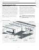
VERSATEC BASE 50Hz SERIES INSTALLATION MANUAL Installing Horizontal Units Use only the bolts provided in the kit to attach hanger brackets. The use of longer bolts could damage internal parts. Some applications require the installation of horizontal units on an attic floor. In this case, the unit should be set in a full size secondary drain pan on top of a vibration absorbing pad. The secondary drain pan prevents possible condensate overflow or water leakage damage to the ceiling.
VERSATEC BASE SERIES 50Hz INSTALLATION MANUAL Hanger Bracket Locations Right D Left F Compressor Section E G Air Handler Section C B Air Handler Section E G D Compressor Section F A 3/8” Threaded Rod (not supplied) Vibration Isolator Washer Hex Nuts (not supplied) Bolt and Lockwasher Weight Distribution Table Hanger Dimensions Hanger Kit Part Number Model 005 006-007 009 010-012 015 017 in. cm. in. cm. in. cm. in. cm. in. cm. in. cm.
VERSATEC BASE 50Hz SERIES INSTALLATION MANUAL Duct System An air outlet collar is provided on vertical top flow units and all horizontal units to facilitate a duct connection. A flexible connector is recommended for discharge and return air duct connections on metal duct systems. Uninsulated duct should be insulated with a minimum of 1-inch duct insulation. Application of the unit to uninsulated ductwork in an unconditioned space is not recommended as the unit’s performance will be adversely affected.
VERSATEC BASE SERIES 50Hz INSTALLATION MANUAL Water Quality In ground water situations where scaling could be heavy or where biological growth such as iron bacteria will be present, a closed loop system is recommended. The heat exchanger coils in ground water systems may, over a period of time, lose heat exchange capabilities due to a buildup of mineral deposits inside. These can be cleaned, but only by a qualified service mechanic, as special solutions and pumping equipment are required.
VERSATEC BASE 50Hz SERIES INSTALLATION MANUAL System Cleaning and Flushing Cleaning and Flushing Refill the system with clean water. Test the system water for acidity and treat as required to leave the water slightly alkaline (pH 7.5 to 8.5). The specified percentage of antifreeze may also be added at this time. Use commercial grade antifreeze designed for HVAC systems only. Environol™ brand antifreeze is recommended.
VERSATEC BASE SERIES 50Hz INSTALLATION MANUAL Open Loop Ground Water Systems Typical open loop piping is shown below. Always maintain water pressure in the heat exchanger by placing water control valves at the outlet of the unit to prevent mineral precipitation. Use a closed, bladder-type expansion tank to minimize mineral formation due to air exposure.
VERSATEC BASE 50Hz SERIES INSTALLATION MANUAL Freeze Detection For Aurora Base Control, set SW2-1, FP1, on the printed circuit board for applications using a closed loop antifreeze solution to 15°F [-9.4°C]. On applications using an open loop/ground water system (or closed loop no antifreeze), set this dip switch to 30°F [-1.1°C], the factory default setting. (Refer to the Dip Switch Field Selection table).
VERSATEC BASE SERIES 50Hz INSTALLATION MANUAL Electrical Data 5-Speed ECM Motor Compressor Model 005 006 007 009 010 012 015 017 Rated Voltage Voltage Min/ Max MCC RLA LRA 220-240/50/1 220-240/50/1 380-420/50/3 220-240/50/1 380-420/50/3 220-240/50/1 380-420/50/3 380-420/50/3 220-240/50/1 380-420/50/3 380-420/50/3 380-420/50/3 198/264 198/264 342/462 198/264 342/462 198/264 342/462 342/462 198/264 342/462 342/462 342/462 13.1 12.6 6.0 14.0 6.4 17.7 7.1 7.7 25.5 8.0 12.0 11.5 5.5 6.7 2.9 8.0 3.2 9.
VERSATEC BASE 50Hz SERIES INSTALLATION MANUAL Electrical Data cont. Variable Speed ECM Motor Compressor LRA Blower Motor FLA Total Unit FLA Min Circ Amp Max Fuse/HACR Breaker 5.5 24.0 4.0 9.5 10.9 15 12.6 6.7 46.0 4.0 10.7 12.4 15 6.0 2.9 30.0 4.1 7.0 7.7 10/15 198/264 14.0 8.0 46.0 4.0 12.0 14.0 20 342/462 6.4 3.2 30.0 4.1 7.3 8.1 10/15 Model Rated Voltage Voltage Min/Max MCC RLA 005 220-240/50/1 198/264 13.
VERSATEC BASE SERIES 50Hz INSTALLATION MANUAL Blower Performance Data cont.
VERSATEC BASE 50Hz SERIES INSTALLATION MANUAL 5-Speed ECM Constant Torque Motors Signal Connection - 1/4 in. quick connects - Common to C, 24VAC to Taps #1-5. The 5-speed ECM is a ‘Constant Torque’ ECM motor and delivers air flow similar to a PSC but operates as efficiently as an variable speed ECM Motor. Because it’s an ECM Motor, the 5-speed ECM can ramp slowly up or down like the variable speed ECM Motor.
VERSATEC BASE SERIES 50Hz INSTALLATION MANUAL Blower Performance Data cont. Variable Speed ECM Motor Model Max ESP (Pa) Blower Size Motor kW Air Flow Dip Switch Settings 1 2 3 4 5 6 142 189 L 236 283 M 330 H 378 7 8 9 10 11 005 124.50 229 x 178 0.37 006 124.50 229 x 178 0.37 189 L 236 283 M 330 378 H 425 472 519 007 124.50 229 x 178 0.37 189 236 L 283 330 M 378 425 472 H 519 009 124.50 229 x 178 0.
VERSATEC BASE 50Hz SERIES INSTALLATION MANUAL Blower Performance Data cont. Variable Speed ECM Setup with an AID Tool cont. Setting Blower Speed - Variable Speed ECM The ABC board’s Yellow Config LED will flash the current variable speed ECM blower speed selections for low, med, and high continuously with a short pause in between. The speeds can also be confirmed with the AID Tool under the Setup/ECM Setup screen.
VERSATEC BASE SERIES 50Hz INSTALLATION MANUAL Wiring Schematics Aurora Control with UPC To ABC - P8 12345678 Orange Blue Red Green White Brown Black Yellow BACnet or N2 Network Connections COM NET- NET+ COM Optional LON Add-On Module NET- NET+ Devices Must Be Wired in Daisy Chain Configuration POWER LON OC GND NET+ 24 VAC NETLON Network Connections LED3 POWER NET+ LED2 RX FORMAT BATT N/C Communication Options Signal ECHELON 1 Tx LED3 Rx LED4 LED6 TX LED7 RX 2W 4W 1 2
VERSATEC BASE 50Hz SERIES INSTALLATION MANUAL Wiring Schematics cont.
VERSATEC BASE SERIES 50Hz INSTALLATION MANUAL Wiring Schematics cont.
VERSATEC BASE 50Hz SERIES INSTALLATION MANUAL Wiring Schematics cont.
VERSATEC BASE SERIES 50Hz INSTALLATION MANUAL Wiring Schematics cont.
VERSATEC BASE 50Hz SERIES INSTALLATION MANUAL Controls - Aurora Base Control Aurora ‘Base’ Control Field Selectable Options via Hardware DIP Switch (SW1) – Test/Configuration Button (See SW1 Operation Table) Test Mode The control is placed in the test mode by holding the push button switch SW1 for 2 - 5 seconds. In test mode most of the control timings will be shortened by a factor of sixteen (16). LED3 (green) will flash at 1 second on and 1 second off.
VERSATEC BASE SERIES 50Hz INSTALLATION MANUAL Controls - Aurora Base Control cont. Cycle with Blower - The accessory relay will cycle with the blower output. Lockout – when locked out, the blower will operate continuously in “G” speed, and PSC blower motor output will remain on. The Alarm output (ALM) and Lockout output (L) will be turned on. The fault type identification display LED1 (Red) shall flash the fault code.
VERSATEC BASE 50Hz SERIES INSTALLATION MANUAL Controls - Aurora Base Control cont. Over/Under Voltage Shutdown - An over/under voltage condition exists when the control voltage is outside the range of 18 VAC to 30 VAC. If the over/under voltage shutdown lasts for 15 minutes, the lockout and alarm relay will be energized. Over/under voltage shutdown is selfresetting in that if the voltage comes back within range of 18 VAC to 30 VAC for at least 0.5 seconds, then normal operation is restored.
VERSATEC BASE SERIES 50Hz INSTALLATION MANUAL Controls - Aurora Base Control cont. Aurora ‘Base’ Control LED Displays Aurora Interface and Diagnostics (AID) Tool These three LEDs display the status, configuration, and fault codes for the control. These can also be read in plain English via the Aurora AID Tool. The Aurora Interface and Diagnostics (AID) Tool is a device that is a member of the Aurora network.
VERSATEC BASE 50Hz SERIES INSTALLATION MANUAL Controls - UPC DDC Control (optional) Aurora UPC Controller ZS Series Sensors and communicate to the heat pump thru a choice of 3 different communication protocols. The Aurora UPC has the ability to communicate BACnet MS/TP, N2 open, or LonWorks (requires LON Plugin card). This flexibility is possible due to the onboard dipswitches which allow for the desired protocol and baud rate to be selected in the field.
VERSATEC BASE SERIES 50Hz INSTALLATION MANUAL Controls - UPC DDC Control (optional) cont.
VERSATEC BASE 50Hz SERIES INSTALLATION MANUAL Controls - UPC DDC Control (optional) cont. Port 1a is used to communicate to the Building Automation System (BAS). This port’s settings are configured through the onboard dip switches. 24Vac Port 2 is used to communicate to the Aurora Base Controller (ABC). Dip switches for configuring the communication port protocol and baud rate for the BAS port. Port 1b is used for the LonWorks plugin. Rnet port is used for communicating zone sensors.
VERSATEC BASE SERIES 50Hz INSTALLATION MANUAL Controls - UPC DDC Control (optional) cont. 1. Leaving Air Temperature (LAT) Sensor – This 10 kOhm NTC sensor is factory installed on all UPC equipped heat pumps. It typically is attached to wiring inside the blower cabinet on the suction side of the blower. This sensor is attached on ABC FP2 pins available as LAT AU-30. 1.
VERSATEC BASE 50Hz SERIES INSTALLATION MANUAL Controls - UPC DDC Control (optional) cont.
VERSATEC BASE SERIES 50Hz INSTALLATION MANUAL Controls - UPC DDC Control (optional) cont. Aurora Advanced Control Configuration and Options (Future Availability on Select Models/Configurations) 1. Accessory Relay2 – A second, configurable, accessory relay on the AXB is provided that can be cycled with the compressor 1 or 2 , blower, or the Dehumidifier (DH) input. This is to complement the Accessory 1 Relay on the ABC board.
VERSATEC BASE 50Hz SERIES INSTALLATION MANUAL Controls - UPC DDC Control (optional) cont. Aurora Advanced Control Optional Sensor Kits (Future Availability on Select Models/Configurations) 1. Energy Monitoring (Standard Sensor Kit on ‘Advanced’ models) - The Energy Monitoring Kit includes two current transducers (blower and electric heat) added to the existing two compressor sensors so that the complete power usage of the heat pump can be measured.
VERSATEC BASE SERIES 50Hz INSTALLATION MANUAL Controls - UPC DDC Control (optional) cont. This is done using (2) 18 AWG twisted pair unshielded cables for a total of 4 wires connected to the Rnet port. The sensor gets its power from the UPC controller and connecting multiple sensors to one UPC will allow for space temperature averaging. The UPC can support one ZS Pro or ZS Pro F with up to four ZS standard sensors wired to the Rnet port on the UPC for a total of 5 zone sensors.
VERSATEC BASE 50Hz SERIES INSTALLATION MANUAL Controls - UPC DDC Control (optional) cont. RNet Sensor Physical and Electrical Data Sensing Element Range Accuracy Temperature (on non-Humidity models) (-20° C to 50° C) (0.2° C) (10° C to 40° C) (0.3° C) Temperature (on Humidity models) Humidity 10% to 90% ±1.
VERSATEC BASE SERIES 50Hz INSTALLATION MANUAL Unit Startup Before Powering Unit, Check The Following: NOTE: Remove and discard the compressor shipping bolts. The bolts can then be discarded. • High voltage is correct and matches nameplate. • Fuses, breakers and wire size correct. • Low voltage wiring complete. • Piping completed and water system cleaned and flushed. • Air is purged from closed loop system. • Isolation valves are open, water control valves or loop pumps wired.
VERSATEC BASE 50Hz SERIES INSTALLATION MANUAL Operating Parameters Single Speed Models SI Cooling -- No Hot Water Generation Entering Water Water Flow Temp L/s/kW °C 21.1 32.2 43.3 Discharge Pressure kPa Water Temp Superheat Subcooling Rise °C Air Temp Drop °C DB 0.09 793 - 862 1034 - 1172 11 - 19 6-9 9 - 12 9 - 13 0.19 724 - 827 896 - 1000 11 - 19 6-9 4-6 9 - 13 0.09 896 - 965 1482 - 1620 7 - 11 4-8 9 - 12 9 - 13 0.19 883 - 951 1310 - 1448 7 - 11 4-8 4-7 9 - 13 0.
VERSATEC BASE SERIES 50Hz INSTALLATION MANUAL Pressure Drop Pressure Drop (kPa) Model 005 006 007 009 010 012 015 017 Pressure L/s 0.19 0.25 0.32 0.38 0.19 0.28 0.38 0.50 0.25 0.38 0.50 0.63 0.32 0.44 0.57 0.76 0.32 0.50 0.69 0.88 0.38 0.57 0.76 1.01 0.57 0.76 0.95 1.26 0.76 0.95 1.14 1.51 Valve -1.11°C 10°C 21.1°C 3.3 4.7 6.2 7.7 3.2 6.1 9.0 12.9 2.4 5.1 7.8 10.5 2.0 3.6 5.2 7.5 2.1 4.8 7.5 10.1 2.7 6.0 9.5 14.2 4.5 6.5 8.6 12.1 5.7 8.9 12.0 17.4 3.2 4.2 5.2 6.2 3.1 5.5 7.9 10.9 2.3 4.9 7.
VERSATEC BASE 50Hz SERIES INSTALLATION MANUAL Thermistor Resistance Thermistor Resistance Thermistor Temperature (°C) Microprocessor Resistance (Ohms) -15 -10 -5 0 5 10 15 20 25 30 35 40 45 50 55 60 72,950 55,330 42,330 32,650 25,390 19,900 15,710 12,490 10,000 8,057 6,530 5,327 4,370 3,603 2,986 2,488 65 2,083 12/5/14 Refrigerant Circuit Guideline Head Pressure Under Charged System (Possible Leak) Low Over Charged System High Low Air Flow Heating High Low Air Flow Cooling Low Low Water Flow Heating
VERSATEC BASE SERIES 50Hz INSTALLATION MANUAL Heat of Extraction/Rejection Data Heat of Extraction/Rejection Heat Of Extraction (HE) Model GPM 005 10°C 21.1°C 32.2°C 3.3 4.4 5.6 0.3 2.5 3.4 4.6 0.3 2.5 3.5 0.2 0.2 006 5.7 5.4 5.0 4.7 5.7 6.5 6.4 5.7 5.5 5.1 8.7 8.0 7.5 8.8 8.1 7.5 6.5 6.5 5.8 6.8 7.0 8.7 0.4 3.3 4.9 6.2 7.1 8.8 5.4 7.2 9.1 5.6 7.4 9.2 0.4 4.2 0.5 3.9 5.8 7.7 9.3 6.3 8.3 10.7 21.1°C 32.2°C 43.3°C 8.8 8.2 7.5 9.9 9.3 8.
VERSATEC BASE 50Hz SERIES INSTALLATION MANUAL Reference Calculations Heating Calculations: LWT = EWT - LAT = EAT + HE WF x 4.2 HC AF x 1.08 Cooling Calculations: LWT = EWT + HR WF x 4.2 LAT(DB) = EAT(DB) - SC AF x 1.08 LC = TC - SC TH = HC + HWC S/T = SC TC Note: Use 4.1 for 15% Methanol/water or Environol solution. Notes (Refer to Performance Data tables) • Performance ratings are based on 27°C DB / 19°C WB EAT for cooling and 20°C DB EAT for heating. • Three flow rates are shown for each unit.
VERSATEC BASE SERIES 50Hz INSTALLATION MANUAL Troubleshooting Should a major problem develop, refer to the following information for possible causes and corrective steps. If compressor won’t run: 1. 2. 3. 4. 5. 6. 7. 8. 9. The fuse may be open or the circuit breaker is tripped. Check electrical circuits and motor windings for shorts or grounds. Investigate for possible overloading. Replace fuse or reset circuit breakers after fault is corrected. Supply voltage may be too low.
VERSATEC BASE 50Hz SERIES INSTALLATION MANUAL Startup and Troubleshooting Form Company Name: _________________________________ Technician Name: ________________________________ Model No: ______________________________________ Owner’s Name: __________________________________ Installation Address: ______________________________ Company Phone No: ______________________________ Date: __________________________________________ Serial No:_______________________________________ Open or Closed Loop: _____________
VERSATEC BASE SERIES 50Hz INSTALLATION MANUAL DEALER: PHONE #: DATE: PROBLEM: MODEL #: Startup/Troubleshooting Form SERIAL #: COOLING CYCLE ANALYSIS PSI = SAT °F °F Unit Amp Draw: °F AIR COIL Loop: Open Closed Line Voltage: °F SUCTION COMPRESSOR COAX COAX EXPANSION VALVE LOAD REVERSING VALVE SOURCE DISCHARGE Hot Water Generator °F °F LIQUID LINE °F °F °F °F PSI PSI PSI PSI °F BRINE IN BRINE IN BRINE OUT SAT °F PSI = Superheat °F Subcooling BRINE OUT Water to Water A
VERSATEC BASE 50Hz SERIES INSTALLATION MANUAL Preventive Maintenance Water Coil Maintenance 1. Keep all air out of the water. An open loop system should be checked to ensure that the well head is not allowing air to infiltrate the water line. Lines should always be airtight. 2. Keep the system under pressure at all times. It is recommended in open loop systems that the water control valve be placed in the discharge line to prevent loss of pressure during off cycles.
VERSATEC BASE SERIES 50Hz INSTALLATION MANUAL Service Parts - Vertical Compressor 220-240/50/1 Compressor 380-420/50/3 005 006 007 009 010 34P593-03 34P636-02 34P637-02 34P635-02 Not Available 34P639-02 Not Available Not Available Not Available 34P636-04 34P637-04 34P635-04 34P638-04 012 015 34P639-04 017 34P630-04 34P631-04 Compressors Run Capacitor 220-240/50/1 16P002D30 16P002D30 Not Available 16D002D35 Not Available Not Available 16P002D29 Sound Jacket 92P523-01 Discharge Muff
VERSATEC BASE 50Hz SERIES INSTALLATION MANUAL Service Parts - Horizontal 005 Compressor 220-240/50/1 Compressor Compressors 380-420/50/3 Run Capacitor 220-240/50/1 34P593-03 006 007 34P636-02 34P637-02 Not Available 34P636-04 34P637-04 16P002D30 Sound Jacket 420/50/3 015 34P639-02 Not Available Not Available 34P635-04 34P639-04 34P638-04 34P630-04 34P631-04 92P524-01 36P503B02 14S551-01 Not Available 017 34P635-02 Not Available 92P523-01 220-240/50/1 VS ECM Motor 380- 012 36P500B01
VERSATEC BASE SERIES 50Hz INSTALLATION MANUAL Notes 53
VERSATEC BASE 50Hz SERIES INSTALLATION MANUAL Revision Guide Pages: All Description: Document Created 54 Date: By: 20 Jan 2015 MA
Manufactured by WaterFurnace International, Inc. 9000 Conservation Way Fort Wayne, IN 46809 www.waterfurnace.com IM1201AUB Product: Type: Size: Document: 01/15 Versatec Base Series Geothermal/Water Source Heat Pump Commercial 0.5-6 Ton Installation Manual All Versatec Base 50Hz product is safety tested to CE standards and performance tested in accordance with standard EN 14511-2. ©2015 WaterFurnace International, Inc., 9000 Conservation Way, Fort Wayne, IN 46809-9794.