2 OPERATING MANUAL GSM2108 and GSM1008-2SFP CORPORATE HEADQUATERS MANUFACTURING/CUSTOMER SERVICE 5001 American Blvd. W., Suite 605 Bloomington, MN 55437 Phone: 800.441.5319 Phone: 952.831.5603 Fax: 952.831.5605 945 37 Avenue, NW Rochester, MN 55901 Phone: 800.328.2275 Phone: 507.252.1951 Fax: 507.285.1952 th Web site: http://www.watersnet.
TABLE OF CONTENTS 1.0 SPECIFICATIONS ........................................................................................................................... 4 2.0 PACKAGE CONTENTS................................................................................................................... 6 3.0 INTRODUCTION.............................................................................................................................. 6 3.1 3.2 3.3 3.4 3.5 3.6 3.7 3.8 3.9 4.0 HARDWARE FEATURES .
5.20 5.21 5.22 5.23 5.23.1 5.23.2 5.23.3 5.24 5.25 5.26 5.27 5.28 5.29 6.0 6.1 6.2 7.0 7.1 8.0 8.1 8.2 8.3 9.0 TRUNKING CONFIGURATION ......................................................................................................... 78 802.1X CONFIGURATION ............................................................................................................. 83 ALARM CONFIGURATION ...............................................................................................................
1.0 Specifications OPERATIONAL CHARACTERISTICS MAC Address Table 8K Switching Mode Store-and-forward Memory Buffer Size 144KB Jumbo frame support Performance Non-blocking wire speed Auto negotiation Auto-MDIX Back pressure flow control for half duplex Flow control for full duplex MANAGEMENT FUNCTIONS Web-based, SNMP (v1, v2c), CLI, or Telnet Port setting for duplex and speed Port trunking (4 groups) Port based and tagged VLANs (up to 256) IGMP snooping 802.
RJ45 shielded female ports 10/100Mbps: CAT5 UTP or better MM or SM with LC connectors POWER SUPPLY: Internal power supply Input Voltage 100 to 240 VAC, 50 to 60Hz Power Consumption 30 watts maximum OPERATING ENVIRONMENT Ambient Temperature: 32° to 122°F (0° to 50°C) Ambient Humidity 0% to 90% MECHANICAL: Enclosure: Rack mountable Cooling Method: Fan cooled PHYSICAL CHARACTERISTICS Dimensions: GSM2108 5.2 x 8.54 x 1.73 in 132 x 217 x 44 mm Dimensions: GSM1008-2SFP 4.72 x 7.56 x 1.38 in 120 x 192.
2.0 Package Contents Examine the shipping container for obvious damage prior to installing this product. Notify the carrier of any damage that you believe occurred during shipment. Ensure that the items listed below are included. If an item is missing, please contact your supplier. 3.
3.
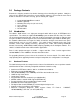
3.3 Hardware Description Figure 3.1 GSM-2108 Switch There are eight 10/100/1000 copper and two SFP fiber ports for optional removable modules on the front panel of the switch. The LEDs, located on the left side of the front panel, contains a power LED indicating the power status and the status of the eight working ports on the switch. TP Port Status: SPEED TP Port Status: Link/ACT SFP Fiber Port Power Indication LED Fiber Port Status Indication RESET Button: RESET button is used management system.
The following table provides the status and description of the LEDs: LED POWER CPU LED Color System LED Green Green Function Lit when +5V DC power is on and good Blinks when CPU is active 10/100/1000Ethernet TP Port 1 to 8 LED Lit when connection with remote device is good LINK/ACT Green Blinks when any traffic is present Off when cable connection is not good Lit green when 1000Mbps speed is active Green/ Lit amber when 100Mbps speed is active 10/100/1000Mbps Amber Off when 10Mbps speed is active SFP(L
3.6 Installation Choose a surface for your switch that is clean, smooth and near a power outlet. Make sure that there is enough clearance around the switch to allow attachment of cables, power cord and air circulation. 1. Plug in the power cord into the switch. 2. Install the proper cable for network connection. 3. Plug the power cord into the power source. 3.7 Optional SFP Modules The SFP modules are hot swappable, so you can plug or unplug the modules before and after the switch is turned on.
The following table describes the cable and devices’ bit-time delay (round trip): 1000Base-X TP, Fiber 100Base-TX TP Round trip Delay: 4096 100Base-FX Fiber Round trip Delay: 512 CAT5 11.12/m CAT5 Fiber 10.10/m TP to fiber converter: 56 Bit time unit: 1ns (1sec./1000 Mega bit) 1.12/m Fiber Cable: 1.0/m Bit time unit: 0.01μs (1sec.
Figure 3-5 - Port-based VLAN Diagram 1. As a member of a VLAN, you cannot be a member of a VLAN in another switch. 2. As a member of a VLAN, you cannot access a member of another VLAN. 3. The switch manager has to assign different names for each VLAN at one switch. group Case 2b: Port-based VLAN (See Figure3-6). Figure 3-6 - Port-based VLAN Diagram This is an example of how VLANs can be set up between two switches. 1. VLAN1 members cannot access VLAN2, VLAN3 and VLAN4 members. 2.
Figure 3.7 - Attribute-based VLAN Diagram 4.0 Network Applications There are three ways to access switch management functions: 1. RS-232 serial port connection (CLI) 2. Telnet 3. Web Note: Before accessing management functions through Telnet or the Web, you must modify the IP address, subnet mask, default gateway and DNS through the RS-232 connection. 4.1 Using the RS-232 Serial Port Connection To configure the switch via the RS-232 serial port connection, follow these steps: 1.
4.2 Configuring IP, Subnet Mask and Default Gateway The default settings for your switch are listed in the following table: Default Value IP Address Subnet Default Gateway GSM2108/GSM1008 192.168.1.1 255.255.255.0 192.168.1.254 Table 4-1 You may either change the IP address of the switch or change the IP address of your workstation. To change the IP address of the switch, via the console connection, you will have to use the CLI command listed below. A complete list of CLI commands is in Section 6.
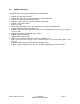
Once you have set the IP address of the switch, you must save the configuration. The CLI command is: save start. A detailed list of CLI commands can be found in Section 6.0. 4.3 Configuring the Switch via the Web You can configure and monitor the switch through: CLI Web browser SNMP manager. The user interface for SNMP is not covered at this time. Assign an IP address, For example: IP = 192.168.1.100 Subnet Mask = 255.255.255.0 Default Gateway = 192.168.1.254 Figure 4.
4.4 IP Address Assignment Figure. 4-3 - Login Screen via a Web browser For IP address configuration, the following three parameters are required: IP address Subnet Mask Default Gateway and DNS. IP Address: The address of the network device is used for internetworking communication. IP addresses are split into predefined address classes or categories. This is referred to as “classful” addressing because the address is spilt into three predefined classes, groupings or categories.
Bit # 0 1 7 8 0 Network address Host address Class B: IP address range between 128.0.0.0 and 191.255.255.255. Each class B network has a 16-bit network prefix followed 16-bit host address. There are 16,384 (2^14)/16 networks able to be defined with a maximum of 65534 (2^16 –2) hosts per network. Bit # 01 2 15 16 10 Network address Host address Class C: IP address range between 192.0.0.0 and 223.255.255.255. Each class C network has a 24-bit network prefix followed 8-bit host address.
networks. For a class B network, 128.1.2.3, the subnet mask 255.255.0.0 in default, in which the first two bytes are all 1s. This means more than 60 thousands of nodes in flat IP address will be at the same network. This is too large to manage practically. Now if we divide it into a smaller network by extending network prefix from 16 bits to, say 24 bits, its third byte is used to subnet this class B network. Now it has a subnet mask 255.255.255.0, in which each bit of the first three bytes is 1.
Prefix Length No. of IP matched No. of Addressable IP /32 1 - /31 2 - /30 4 2 /29 8 6 /28 16 14 /27 32 30 /26 64 62 /25 128 126 /24 256 254 /23 512 510 /22 1024 1022 /21 2048 2046 /20 4096 4094 /19 8192 8190 /18 16384 16382 /17 32768 32766 /16 65536 65534 Table 4-2 According to the scheme above, a subnet mask 255.255.255.0 will partition a network with the class C.
For assigning an IP address to the switch, check the IP address of the network that will be connected to the switch. Use the same network address and append your host address. Figure 4.4 – IP Configuration First, IP Address: as shown in the Figure 4.4, enter 192.168.1.1, for example. An IP address such as 192.168.1.x must be set on your PC. Second, Subnet Mask: as shown in the Figure 4.4, enter 255.255.255.0. Any subnet mask such as 255.255.255.x is allowable in this case.
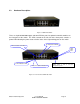
5.0 Web Based Management This section illustrates the configuration and management of the GSM switch through a web interface. Management through the web interface allows you to easily access and monitor the switch through any port. The default values of the managed switch are listed in the table below: IP Address 192.168.1.1 Subnet Mask 255.255.255.0 Default Gateway 192.168.1.
Figure 5.1 – Login Screen 5.1 Overview of Web Management Once you have logged into the switch, the opening screen displays the System Information. On the left side of the screen, the function tree for all of the management functions is displayed. We will explore these functions in this chapter.
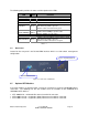
Figure 5.2 – System Information The top of the screen displays the front panel of the switch. The linked ports will be displayed in green and the ports that are not connected will be dark. The optional modules will display a cover plate if no module exists and will show a module if a module is present. The image of module depends on the installed module. If the module port is not connected, the port be dark and, if linked, green.
management functions when you are finished. The Auto Logout default is set to three minutes. You may change the time by using the pull down list for Auto Logout. The system will automatically log out if there has been no activity during the time you choose. There is also an option for OFF. If OFF is selected, the management screen will remain on. The left side of the screen displays the main menu tree for the web functions. This a hierarchical menu.
5.2 System Information Function name: System Information Function description: Show the basic system information. Parameter description: Model name: The model name of this device. System description: Describes the device. “L2 Managed Switch”. Location: The location where this switch is being used. User-defined. Contact: For the purpose of managing and maintaining the device, enter the contact person and phone to be used for help.
Device Port: Show all types and numbers of the port in the switch. RAM size: The size of the DRAM in this switch. Flash size: The size of the flash memory in this switch. 5.3 IP Configuration IP configuration is one of the most important configurations in the switch. Without the proper setting, the network manager will not be able to manage or view the device. The switch supports both manual IP address setting and automatic IP address setting via DHCP server.
DHCP, refer to Section 4.4 - IP Address Assignment. Default: Disabled IP address: Users can configure the IP settings and enter new values if users set the DHCP function to “Disable”. Click the Apply button to update. When DHCP is disabled, Default: 192.168.1.1 If DHCP is enabled, this field is completed by the DHCP server and will not allow user manually set future IP addresses. Subnet mask: The purpose of the subnet mask is to get more network addresses.
5.4 Time Configuration The switch provides a manual and automatic method to set the system time via NTP. Manual setting is simple. Input “Year”, “Month”, “Day”, “Hour”, “Minute” and “Second” within the valid value range indicated in each item. If you input an invalid value, for example, 61 in minute, the switch will clamp the figure to 59. NTP is a well-known protocol used to synchronize the system time of the switch system time over a network.
since it passed over. The switch supports valid configurable daylight saving time is –5 ~ +5 step one hour. The zero for this parameter means it need not have to adjust current time, equivalent to in-act daylight saving. You don’t have to set the starting/ending date as well. If you set daylight saving to be non-zero, you have to set the starting/ending date as well; otherwise, the daylight saving function will not be activated. Default for Daylight Saving: 0.
Figure 5.5 – System Time Setting 5.5 Account Configuration Only the administrator can create, modify or delete the username and password. The administrator can modify other guest identities’ password without confirming the password. Guest-equivalent identity can modify his password only. Please note that you must confirm administrator/guest identity in the field of Authorization in advance before configuring the username and password. Only one administrator is allowed to exist and unable to be deleted.
Through the management security configuration, the manager can perform the setup to control the switch and limit user to access the switch. The following rules are provided for the management of the switch: Rule 1: If no lists exists, all connections are accepted. Accept __________________________________________________ Rule 2: If “accept lists” exists, all connections will be denied except the connection inside the accepting range.
connected by via HTTP, Telnet or SNMP. Figure 5.7 – Management Security Configuration Parameter description: Name: A name is composed of any letter (A-Z, a-z) and digit (0-9) with maximal 8 characters. VID: The switch supports two options for managed valid VLAN VID, including any and custom. The default is any. Custom allows you to supply the VID number. The valid VID range is 1~4094. IP Range: The switch supports two options for managed valid IP Range, including any and custom. The default is any.
5.7 Virtual Stack Function name: Virtual Stack Function description: Virtual Stack Management (VSM) is the group management function. VSM configuration automatically groups switches in the same LAN. One switch among the group will be the master device, and the others will become the slave devices. VSM offers a simple centralized management function. It is not necessary to remember the address of all devices, because the manager is capable of managing the network with the address of the Master device.
Figure 5.8 – Virtual Stack Parameter description: State: Used for the activation or de-activation of VSM. Role: The role that the switch would like to play in virtual stack. Two types of roles, including master and slave are offered. The default is Master. Group ID: It is the group identifier (GID) which signs for VSM. Valid letters are A-Z, a-z, 0-9, “ - “ and “_” characters. The maximum length is 15 characters. Figure 5.
5.8 Port Configuration Port configuration includes the following functions: Port Configuration Status Configuration Simple Counter Detail Counter 5.8.1 Port Status The port status function gathers the current status for all ports. The information is displayed by the order of port number, link status, port state, auto-negotiation status, speed/duplex and flow control. If a fiber module is installed in one or both of the slots, the current status for those ports will be displayed. See Figure 5.10.
Displays the port number. The number is 1 – 8. Ports 7 and 8 may be fiber modules. Media: Shows the media type used in all ports. Port 7 and Port 8 are dual media ports, which support either fiber or UTP media with either Gigabit Ethernet or Fast Ethernet. If SFP modules are installed, Port 7 and/or Port 8 can no longer be used for a UTP connection.
Displays the speed and duplex mode of all ports. There are three speeds 10Mbps, 100Mbps and 1000Mbps supported for TP media. Duplex mode is half duplex and full duplex. If the media is 1Gbps fiber, it is 1000Mbps only. The status of speed/duplex mode is determined by: Negotiation of both the local port and the link partner in “Auto Speed” mode User setting in “Force” mode. The local port has to be preset according to its capability. Default: None, depends on the result of the negotiation.
Vcc: Displays the working DC voltage of SFP module. Mon1(Bias) mA: Displays the Bias current of SFP module. Mon2(TX PWR): Displays the transmit power of SFP module. Mon3(RX PWR): Displays the receiver power of SFP module. 5.8.2 Port Configuration Port Configuration is used to modify the setting by port. This function allows set and reset the functions described below. Figure 5.12 – Port Configuration Function name: Port Configuration Function description: Used to set the operation mode of each port.
transmitted and received via this port. When disabled, the port is blocked and no traffic can be transmitted through this port. Port State is configurable by the user. If you set a port’s state to Disable, then that port cannot pass traffic, even though Link is displayed. Default: Enable. Mode: Set the speed and duplex mode for the port. If the media is 1Gbps fiber, it will always be 1000Mbps and the duplex mode can only be full.
Function name: Simple Counter Function description: Displays the summary counting of each port’s traffic, including Tx Byte, Rx Byte, Tx Packet, Rx Packet, Tx Collision and Rx Error Packet. Parameters description: Tx Byte: Total transmitted bytes. Rx Byte: Total received bytes. Tx Packet: The counting number of the packets transmitted. Rx Packet: The counting number of the packet received. Tx Collision: Number of collisions transmitting frames experienced. Rx Error Packet: Number of bad packets received.
Figure 5.14 – Detailed Counter Function name: Detail Counter Function description: Displays the detailed counting number of each port’s traffic. In Figure 5.14, the window shows all counter information for one port at a time. Parameter description: Rx Packets: The counting number of the packets received. RX Octets: Total received bytes. Rx High Priority Packets: Number of Rx packets classified as high priority. Rx Low Priority Packets: Number of Rx packets classified as low priority.
Tx Low Priority Packets: Number of Tx packets classified as low priority. Tx Broadcast: Shows the counting number of the transmitted broadcast packet. Tx Multicast: Shows the counting number of the transmitted multicast packet. Rx 64 Bytes: Number of 64-byte frames in good and bad packets received. Rx 65-127 Bytes: Number of 65 ~ 126-byte frames in good and bad packets received. Rx 128-255 Bytes: Number of 127 ~ 255-byte frames in good and bad packets received.
Rx Fragments: Number of short frames (< 64 bytes) with invalid CRC. Rx Jabber: Number of long frames(according to max_length register) with invalid CRC. Rx Drops: Frames dropped due to the lack of receiving buffer. Rx Errors: Number of the error packets received. Tx Collisions: Number of collisions transmitting frames experienced. Tx Drops: Number of frames dropped due to excessive collision, late collision, or frame aging. Tx FIFO Drops: Number of frames dropped due to the lack of transmitting buffer.
5.9 Mirror Configuration Function name: Mirror Configuration Function description: Mirror Configuration is used to monitor the traffic of the network. For example, if Port A and Port B are Monitoring Port and Monitored Port respectively, the traffic received by Port B will be copied to Port A for monitoring. Note: When configuring the mirror function, it is recommended to avoid setting a port to be a sniffer port and an aggregated port at the same time.
Note: Each port on the switch has a 16KB packet buffer. The packet buffer size will be reduced when the bandwidth rate limitation is enabled, which may cause the jumbo frame to not be forwarded. It is recommended to avoid enabling jumbo frame and bandwidth rating functions at the same time. Figure 5.16 – Bandwidth Management Configuration Parameter description: Port Number: Choose the port to use for bandwidth management. Valid range of the port is 1~8.
5.11 QoS (Quality of Service) Configuration The switch provides the following powerful QoS functions: Per Port Priority VLAN Tag Priority IP TOS Classification IP TCP/UDP Port Classification IP DIffServe Classification Click on Configure next to the desired QoS function. Once you have set the configurations, remember to click on Apply to save the settings. With QoS configurations, the Default Class is either set to high or low.
Choose the port (1~8) respectively with Priority Class on Per Port Priority function. Class: Set High Priority or Low Priority for each port respectively. Figure 5.18 – Per Port Priority Function name: VLAN Tag Priority Function description: In VLAN tag, there are three bits belonging to priority. According to these three bits, we could arrange eight traffics –0 0 0, 0 0 1, 0 1 0, 0 1 1, 1 0 0, 1 0 1, 1 1 0, 1 1 1. We can set High priority or Low priority for each traffic class.
Parameter description: Quality of Service (QoS) VLAN Tag Configuration: Used for setting up the QoS belongs to VLAN operation. Port: Set the ports (1~8) respectively to allow the VLAN Tag QoS function to work. Use Select All to set all the ports at the same time. Bit 0, Bit 1, Bit 2: According to the arrangement of VLAN-tagged priority, eight types of traffic can be formed, including 0 0 0, 0 0 1, 0 1 0, 0 1 1, 1 0 0, 1 0 1, 1 1 0 and 1 1 1.
Port: Set the ports (1~8) respectively to allow the TOS QoS function to work. Use Select All to set all the ports at the same time. Bit 0, Bit 1, Bit 2: According to the arrangement of Bit 5 ~ Bit 7 in TOS Field of IP Header, eight types of traffic can be formed, including 0 0 0, 0 0 1, 0 1 0, 0 1 1, 1 0 0, 1 0 1, 1 1 0 and 1 1 1. Class: Set High Priority or Low Priority for each port respectively for the eight types of traffic.
FTP and news as the QoS of L4 and enter the “Advanced Mode”, then we can see that special port numbers 80, 280, 443, 25, 110, 20, 21, 69, 119, 2009 have already been configured. You can also modify these port numbers. See Figure 5.21. Special TCP/UDP class: There are two modes for selection, including Low and High. Default class (all other TCP/UDP ports): There are two modes for selection, including Low and High.
Figure 5.21 - Advanced Mode Figure 5.22 - Simple Mode Simple Mode: Select Simple to return to the screen that all L4 port number will disappear (See Figure 5.22). Function name IP Diffserv Classification Function description: In the late 1990s, the IETF redefined the meaning of the 8-bit SERVICE TYPE field to accommodate a set of differentiated services (DS).
Class: 64 types of traffic. Can set High Priority or Low Priority for each port respectively. Figure 5.23 – IP Differentiated Services 5.12 SNMP Configuration Any Network Management System (NMS) running the Simple Network Management Protocol (SNMP) can manage devices equipped with the SNMP agent, provided that the Management Information Base (MIB) is installed correctly on the managed devices. SNMP is a protocol that is used to govern the transfer of information between SNMP manager and agent.
If they both have the same community name, they can talk each other. Community name is user-definable with a maximum length of 15 characters and is case sensitive. No blank spaces are permitted in the community name string. Any printable character is allowed. The community name for each function works independently. Each function has its own community name. The community name for GET only works for the GET function and can’t be applied to other function such as SET and Trap.
5.13 IGMP Snooping IGMP snooping is used to establish the multicast groups to forward multicast packets to member ports. IGMP snooping avoids wasting the bandwidth while IP multicast packets are running over the network. A switch that does not support IGMP snooping cannot tell a multicast packet from broadcast packet, so it treats them as broadcast packets. Without IGMP snooping, the multicast packet forwarding function is no different from broadcast packets.
Passive: In passive snooping mode, IGMP snooping will not periodically poll the hosts in the groups. The switch will send a Membership Query message to all hosts only when it has received a Membership Query message from a router. IP Address: Shows all multicast groups IP addresses that are registered on this device. VLAN ID: Shows VLAN ID for each multicast group. Member Port: Shows member ports that join each multicast group. 5.14 Maximum Packet Length Function name: Max.
The switch supports a random delay time for DHCP and boot delay for each device. This suppresses the broadcast storm while all devices are booting at the same time. The maximum user-defined delay time is 30 seconds. If DHCP Broadcasting Suppression function is enabled, the delay time is set randomly, ranging from 0 to 30 seconds. The exact delay time is computed by the switch itself. The default is Disable. Figure 5.27 – DHCP Boot 5.16 VLANs The switch supports Tag-based VLAN (802.
communicate with those ports. Each port-based VLAN must be assigned a group name. This switch can support up to a maximum of 8 port-based VLAN groups. Tag-based: Tag-based VLAN identifies its member by VID. Tag-based VLANs are different from portbased VLANs. If there are additional rules in ingress filtering list or egress filtering list, the packet will be screened with filtering criteria to determine if it can be forwarded. The switch supports 802.1q.
Figure 5.29 – VLAN Mode 5.16.2 Tag-based Group Function name: Tag-based Group Configuration Function description: Displays tag-based VLAN groups. Use this option to create, edit and delete a tag-based VLAN groups. Add a new VLAN group by inputting a new VLAN name and VLAN ID. Parameter description: VLAN Name: Valid letters are A-Z, a-z, 0-9, “ - “ and “_” characters. The maximal length is 15 characters. VID: VLAN identifier. Each tag-based VLAN group has a unique VID used in tag-based and Doubletag mode.
Figure 5.30 – Tag-based Group Add Group: Create a new Tag-based VLAN. Input the VLAN name and the VID. Configure the SYM-VLAN function and choose the member by selecting the check box beside the port number. Press Apply so the settings will take effect. Figure 5.
Delete Group: Press Delete to remove the selected group entry from the tag-based group table. Figure 5.32 – Tag-based Group Edit a group: Select a group entry and select Edit. This allows you to modify the group’s description, SYMVLAN and member set. 5.16.3 Port-Based Group Function name: Port-based Group Configuration Function description: Displays the information for the existing port-based VLAN groups. Use this function to create, edit and delete a port-based VLAN group.
Parameter description: VLAN Name: Valid letters are A-Z, a-z, 0-9, “ - “ and “_” characters. The maximum, length is 15 characters. Member: Used to enable or disable a member port. Enable means the port is a member of the VLAN. Select the check box (;) beside the port x to enable it. Figure 5.33 – Port-based Group Add Group: Create a new port-based VLAN. Input the VLAN name and choose the group member by selecting the check box beside the port number. Select Apply so the setting will take effect.
Figure 5.35 – Port-based Group Edit a group: To edit a group entry, use Edit. This allows you to modify a group‘s description and member set. 5.16.4 Tag Rule Function name: Tag Rule Function description: With the VLAN Tag Rule Setting, input a VID number to each port. The range of VID number is from 1 to 4094. You can choose ingress filtering rules for each port.
packet with VID=100 (VLAN name=VLAN100), and if rule 1 is enabled, the switch will check if port 1 is a member of VLAN100. If it is, the received packet is forwarded; otherwise, the received packet is dropped. Rule 2: Drop untagged frame. You can configure a given port to accept all frames (Tagged and Untagged) or only tagged frames. If you choose all frames, the packets with tagged or untagged will be processed. If you choose only tagged frames, only the packets carrying VLAN tag will be processed.
Displays the static or dynamic learning MAC entry and the state for the selected port. Parameter description: Port: Select the port. Search: Set up the MAC entry. The default is ??-??-??-??-??-?? MAC: Displays the MAC address of the entry selected from the searched MAC entries table. Alias: Set up the Alias for the selected MAC entry. Set Alias: Save the Alias of MAC entry you set up. Search: Find the entry that meets your setup. Previous Page: Move to the previous page. Next Page: Move to the next page.
Figure 5.37 – MAC Table Information Function Name: MAC Table Maintenance Function Description: This function allows the user to set up the processing mechanism of the MAC Table. An idle MAC address exceeding MAC address age-out time will be removed from the MAC Table. The range of age-out time is 10-65535 seconds, and the setup of this time will have no effect on static MAC addresses.
Function Name: Static Forward Function Description: Static Forward is a function that allows the user in the static forward table to access a specified port of the switch. The static forward table associated with a specified port of a switch is set up by manually inputting MAC address and an alias’ name. When a MAC address is assigned to a specific port, all of the switch’s traffic is sent to this MAC address will be forwarded to this port.
Function name: Static Filter Function Description: Static Filter is a function that denies the packet forwarding if the packet’s MAC Address is listed in the filtering Static Filter table. Maintain the table by filling in MAC Address, VID (VLAN ID) and Alias fields individually. You can delete the entry by using Delete. Parameter description: MAC: Six-byte Ethernet hardware address and usually expressed by hex and separated by hyphens. For example, 00 – 40 - C7 - D6 – 00 - 02 VID: VLAN identifier.
Function name: MAC Alias Create/Edit or Delete Function description: In the MAC Alias function, MAC Alias Add/Edit function is used to let you add or modify an association between MAC address and an English name. Select Create/Edit to add a new record with name. Select the MAC Alias Delete function to remove an alias name from a MAC address. You can select an existing MAC address or alias name for removal. Figure 5.
5.18 GVRP Configuration GVRP is an application based on the Generic Attribute Registration Protocol (GARP), mainly used to automatically and dynamically maintain the group membership information of the VLANs. GVRP provides the VLAN registration service through a GARP application. The GARP Information Declaration (GID) is used to maintain the ports associated with their attribute database and GARP Information Propagation (GIP) to communicate among switches and end stations.
Used to declare the Join Time in unit of centisecond. Valid time range: 20 –100 centisecond, Default: 20 centisecond. Leave Time: Used to declare the Leave Time in unit of centisecond. Valid time range: 60 –300 centisecond, Default: 60 centisecond. Leave All Time: A registered device will be de-registered at the end of this time period. If someone still issues a new join, then a registration will be kept in the switch. Valid range: 1000-5000 unit time, Default: 1000 unit time.
Function name: GVRP Counter Function description: GVRP counters are divided into Received and Transmitted categories which allows you monitor the GVRP actions. They are GARP packets. Figure 5.43 – GVRP Counter Parameter description: Received: Total GVRP Packets: Total GVRP BPDU received by the GVRP application. Invalid GVRP Packets: Number of invalid GARP BPDU received by the GARP application. LeaveAll Message Packets: Number of GARP BPDU with Leave All message received by the GARP application.
Total GARP BPDU transmitted by the GVRP application. Invalid GVRP Packets: Number of invalid GARP BPDU transmitted by the GVRP application. LeaveAll Message Packets: Number of GARP BPDU with Leave All message transmitted by the GARP application. JoinEmpty Message Packets: Number of GARP BPDU with Join Empty message transmitted by the GARP application. JoinIn Message Packets: Number of GARP BPDU with Join In message transmitted by the GARP application.
Figure 5.44 – GVRP VLAN 5.19 Spanning Tree Configuration (STP) Configuration The Spanning Tree Protocol (STP) is a standardized method (IEEE 802.1D) used to avoid loops in switched networks. When STP is enabled, only one path is active between any two nodes on the network at a time. Once Spanning Tree Protocol has been enabled, advanced functions can be configured. It is recommend that STP is enabled to ensure a single active path on the network. 5.19.
Displays port number connected to root bridge with the lowest path cost. Root Path Cost: Displays the path cost between the root port and the designated port of the root bridge. Current Max. Age: Displays the current root bridge maximum age time. Maximum age time is used to monitor STP topology.
5.19.2 STP Configuration STP includes Rapid Spanning Tree Protocol (RSTP). STP has six parameters to be configured. These parameters are described below. Function name: STP Configuration Function description: Set the following Spanning Tree parameters to control STP function (enable/disable). Select mode RSTP/STP and affect STP state machine behavior to send BPDU in the switch. The default setting of STP is Disable. Parameter description: Spanning Tree Protocol: Set 802.
Figure 5.46 – STP Configuration 5.19.3 STP Port Configuration Function name: STP Port Setting Function description: In the STP Port Setting, one item selection and five parameters are available for setup. You can disable and enable each port. You can set “Path Cost” and “Priority” for each port and set “Admin Edge Port” and “Admin Point To Point”. Parameter description: Port Status: Displays the current state of a port for viewing only. There are three possible states. ( according to 802.
Configured Path Cost: The range is 0 – 200,000,000. If the path cost is set to zero, the STP will get the recommended value resulted from auto-negotiation of the link accordingly and display this value in the field of Path Cost Status. Otherwise, the value set by the administrator set up will be displayed. 802.1w RSTP recommended value: (Valid range: 1 – 200,000,000) 10 Mbps : 2,000,000 100 Mbps : 200,000 1 Gbps : 20,000 Default: 0 Priority: Port Priority and Port Number are combined to form the Port ID.
Figure 5.47 – STP Port Configuration 5.20 Trunking Configuration The Port Trunking Configuration is used to configure the settings of Link Aggregation. More than one port can be bundled with the same speed, full duplex and the same MAC to be a single logical port. The logical port aggregates the bandwidth of these ports. This means you can apply your current Ethernet equipment to build the bandwidth aggregation.
The switch supports a maximum of eight trunk groups for LACP and additional eight trunk groups for Static Trunk. In the system capability view, only eight “real trunked” groups are supported. An LACP trunk group with more than one ready member-ports is a “real trunked” group. An LACP trunk group with only one or less than one ready member-ports is not a “real trunked” group. Any Static trunk group is a “real trunked” group. Per Trunking Group supports a maximum of 12 ready member-ports.
An Active LACP port begins to send LACPDU to its link partner as soon as the LACP protocol entity takes control of this port. Passive: A Passive LACP port will not actively send LACPDU out until it receives an LACPDU from its link partner. Aggtr: Aggtr is an abbreviation of “aggregator”. Every port is also an aggregator, and its own aggregator ID is the same as its own port number. An aggregator is a representative of a trunking group.
Member Ports: Displays all member ports of an aggregator (port). Ready Ports: Displays only the ready member ports within an aggregator (port). Figure 5.49 – Aggregator View Function name: LACP Detail (LACP Aggregator Detailed Information) Function description: Displays the detailed information of the LACP trunking group. Parameter description: Actor: The switch you are using to view LACP. Partner: The peer system from the aggregator’s view. System Priority: Displays the System Priority of a system ID.
Trunk Status: Displays the trunk status of a single member port.”---“ means “not ready” Figure 5.50 – Aggregator Information Function name: LACP System Priority Function description: Used to set the priority of the LACP system ID. LACP will only aggregate together the ports whose peer link partners are all on a single system. Each system supports LACP will be assigned a globally unique System Identifier for this purpose.
5.21 802.1X Configuration 802.1X port-based network access control provides a method to restrict users to access network resources via authenticating user’s information. This restricts users from gaining access to the network resources through a 802.1X-enabled port without authentication. To access the network through a port under 802.1X control, you must first input your account name for authentication and wait to gain authorization before sending or receiving any packets from a 802.1X-enabled port.
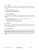
the authenticator to perform authentication message exchange or access the network from the uncontrolled port. Authenticator’s System Supplicant’s System Services Offered by Authenticator (e.g Bridge Relay) Supplicant PAE Controlled port Authenticator PAE Authentication Server’s System Authentication Server Uncontrolled port Port Authorize MAC Enable LAN Figure 5.52 Figure 5.53 represents a typical configuration; a single supplicant, an authenticator and an authentication server.
Figure 5.54 illustrates the procedure of 802.1X authentication. There are steps for the login based on 802.1X port access control management. The protocol used in the right side is EAPOL and the left side is EAP. 1. At the initial stage, supplicant A is unauthenticated so the port acting as an authenticator is in unauthorized state. Access is blocked in this stage. 2. Either authenticator or supplicant can initiate the message exchange.
Bridge LAN PC Radius Server Port connect Access blocked EAPOL-Start EAP EAPOL Radius Authenticator EAP-Request/Identity Radius-Access-Request EAP-Response/Identity Radius-Access-Challenge EAP-Request Radius-Access-Request EAP-Response (cred) Radius-Access-Accept EAP-Success EAP-Failure EAP-Logoff Access allowed Figure 5.54 The type of authentication supported in the switch is multihost 802.1x.
Function name: 802.1X State Setting Function description: This function is used to configure the global parameters for RADIUS authentication in 802.1X port security application. Parameter description: Radius Server: RADIUS server IP address for authentication. Default: 192.168.1.1 Port Number: The port number to communicate with RADIUS server for the authentication service. The valid value ranges 1-65535. Default port number is 1812.
802.1X Mode: 802.1X operation mode. There are two options, including Disable and Multihost mode. Default is Disable. Disable The chosen port acts as a plain port, which means 802.1X port access control does not work on the port. 802.1X with multihost In multihost mode, the devices connected to this port can access the network, once a supplicant is authorized. Figure 5.56 – 802.1X Mode Setting Function name: Port Security Management Function description: Displays each port status.
Select 802.1X with Multihost mode for a port. With the function 802.1X Port Mode Configuration, devices can access the network through this port once the authenticator is authorized. The Port Status will display the following screen. If the port is granted to access the network, the port status is authorized, otherwise, unauthorized. Figure 5.57 – Port Security Management Function name: Parameter Setting Function description: This function is used to configure the parameters for each port in 802.
txPeriod (1-65535 s): A time period to transmitted EAPOL PDU between the authenticator and the supplicant. Default: 30 Quiet Period (0-65535 s): A period of time during in which access the supplicant will not be attempted. Default: 60 seconds reAuthEnabled: Choose whether regular authentication will take place in this port. Default: ON reAuthPeriod (1-65535 s): A non-zero number seconds between the periodic re-authentication of the supplicant. Default: 3600 max.
5.22 Alarm Configuration Alarm Configuration Events Configuration Email/SMS Configuration Function name: Events Configuration Function description: The Trap Events Configuration function is used to enable the switch to send out trap information while pre-defined trap events occur. The switch provides 24 different trap events. The trap information can be sent out in three ways, including email, mobile phone SMS (short message system) and trap.
Function name: Email/SMS Configuration Function description: Alarm configuration is used to configure the recipients of the alarm message via email or SMS, or both. The method is dependent on the settings. An email address or a mobile phone number has to be set in the alarm configuration (See Figure 5.60). If set properly, you can read the trap information from your email or mobile phone. This function provides up to six email addresses and up to six mobile phone numbers.
5.23 Configuration The switch supports three copies of configurations, including the default configuration, working configuration and user configuration for your configuration management. The three copies are described below: Note: If you make changes to the configuration, you must save the configuration before rebooting the switch. Default Configuration: The factory setting and cannot be altered.
5.23.1 Save/Restore Function name: Save As Start Configuration Function description: Save the current configuration as a start configuration file in flash memory. Figure 5.62 - Configuration Function name: Save As User Configuration Function description: Save the current configuration as a user configuration file in flash memory. Figure 5.
5.23.2 Restore Default Function name: Restore Default Configuration (includes default IP address) Function description: Restore Default Configuration function can retrieve the factory setting to replace the start configuration. If the factory settings are restored, the IP address of the switch will be restored to 192.168.1.1. Figure 5.
Function name: Restore User Configuration Function description: Restore User Configuration function retrieves the previous confirmed working configuration stored in the flash memory to update start configuration. When restoring the configuration, the system’s start configuration is updated and will be changed its system settings after rebooting the system. Figure 5.66 – Restore Configuration 5.23.
Figure 5.67 – Configuration Import/Export 5.24 Diagnostics Three functions, including Diagnostics, Loopback Test and Ping Test are available for device self-diagnostics. Each of them will be described in detail in the following sections. Diagnostics Diagnostics Loopback Test Ping Test Function name: Diagnostics Function description: Diagnostics provides a set of basic system diagnosis. Diagnostics provides tests to see if the system in working order.
Figure 5.68 - Diagnostics Function name: Loopback Test Function description: In the Loopback Test function, there are two loopback tests -- Internal Loopback Test and External Loopback Test. The former test function will not send the test signal outside the switch box. The test signal only wraps around in the switch. The second function will send the test signal to its link partner. If the switch is not connected to active network devices, i.e.
Ping Test function is a tool for detecting whether or not the target device is making a connection through the ICMP protocol which submits report messages. The switch provides Ping Test function to let you know whether the target device is available or not. You can simply fill in a known IP address and then click Ping. After a few seconds, the switch will report to the pinged device the result of the Ping. Parameter description: IP Address: An IP address with the version of v4, e.g. 192.168.1.1.
Figure 5.71 – TFTP Server 5.26 Log Data This function displays the log data. The switch provides system log data for users. There are nineteen private trap logs and five public trap logs. The switch supports a total 120 log entries. For more details on log items, please refer to Section 5.22 for Trap/Alarm Configuration and SNMP Configuration.
Parameter description: No.: Displays the order number of the traps. Time: Displays the time of the trap. Events: Displays the trap event name. Auto Upload Enable: Switch the enabled or disabled status of the auto upload function. Upload Log: Upload log data through tftp. Clear Log: Clear log data. 5.27 Firmware Upgrade A software upgrade tool is used to upgrade the software functions and to fix or improve the functionality of the switch.
Figure 5.73 – Firmware Upgrade 5.28 Reboot There are a few ways to reboot the switch, including power up, hardware reset and software reset. You can press the RESET button in the front panel to reset the switch. After upgrading software, changing IP configuration or modifying VLAN configurations, you must reboot in order for the new configuration to take effect. Function name: Reboot Function description: Reboot the switch.
5.29 Logout You can manually logout by using Logout function. You can also configure the switch to logout automatically. Function name: Logout Function description: The switch provides and automatic logout to prevent unauthorized users from using the system. If you do not logout and exit the browser, the switch will automatically logout. You can use Auto Logout. Parameter description: Auto Logout: Default is ON (three minutes).
6.0 Operation of CLI Management Section 4 of this manual provides detailed information for console connection to the switch. This section provides detailed syntax and examples for CLI management. 6.1 Login The command-line interface (CLI) is a text-based interface. You can access the CLI through either a direct serial connection to the device or a Telnet session.
6.2 Commands of CLI To see the commands of the mode, please input “?” after the prompt, then all commands will be listed in the screen. All commands can be divided into two categories, including global commands and local commands. The following global commands can be used in any mode: Exit End Help History Logout Save start Save user Restore default Restore user Command instructions residing in the corresponding modes are local commands.
Command Syntax History history Logout logout Restore Default restore default Restore user restore user Save Start save start Save User save user Waters Network Systems Description When you use help, all commands are displayed. This command will help you distinguish between local and global commands. Displays the list of commands you have been using during the session. CLI supports up to 256 records. If no argument is entered, CLI will list total records up to 256.
Command Syntax Description Argument Possible Value : syntax 1, 5-7, available from 1 to 8 : max-times, range 1-10 1 to 8 : 110, default is 2 : syntax, 1, 5-7, available from 1 to 8 : set up 802.1x mode 0:disable the 802.1x function 1:set 802.
Command Syntax Description Argument Possible Value Set serverTimeout set servertimeout : syntax 1, 5-7, available 1 to 8 :timer, range 1~65535 : 1 to 8 :1~6553 5, default is 30 Set state set state This command sets a timer used by the Backend Authentication state machine to determine timeout conditions in the exchanges between the Authenticator and the Supplicant or Authentication Server.
Command Syntax Description Argument Possible Value Del del modify : existing user account : existing user account None Modify Show show Used to delete an existing account Used to modify the username and password of an existing account Used to display the system account, including account name and identity None None Used to remove the configuration of an email address Used to remove the configuration of the server user account and password Used to set up an email addr
Command Syntax Description Argument Possible Value Show show None None Show (alarm) show Used to display the configuration of an alarm event Alarm is used to display the configuration of Trap, SMS or email None None Used to delete SMS phone number Used to delete SMS server, user account and password Used to add SMS phone number <#> : mobile phone number, range 1 to 6 None <#>: 1 to 6 <> Del phonenumber Del serveruser Set phonenumber Set server Set user del phonenumber <#> del server
Command Syntax Description Argument Possible Value None None None None None None None None :filepath and filename :filep ath and filename :filep ath and filename None settings for bandwidth Config-file Export start export start Export userconf Import start export-user conf import start Import userconf Set exportpath import userconf set export-path Used to run the export start function Used to export user-conf function Used to run the import start
Command Syntax Description Argument Possible Value registrar mode of an existing GVRP group per port can be changed. group you have created using the VID.
Command Syntax Description Argument Possible Value hostname Used to set the hostname of the switch :hostname, max 40 characters :hostna me, max 40 characters Use to set the most for IGMP snooping :0:disable 1:active 2:passive None : 0, 1 or 2 Show set igmp_snooping show None IP Disable DHCP disable dhcp None None Enable DHCP enable dhcp : manual or auto Set DNS set dns :set DHCP with either manual or auto mode
Command Show Syntax show <> Search search Description Used to display the MAC alias entry Used to find the relative MAC information in the MAC table show show Used to display all MAC table information <> Set aging set aging Used to set up the age out time of dynamic learning MAC Set flush set flush Show show Used to delete all MACs learned dynamically Used to display the age timer settings <> Add add [alias] Del del
Command Syntax Description Show filter show filter Show forward show forward Used to display the static filter table Used to display the static forward table Management Add Argument Possible Value not tag-based None None None None [ ] No default, must be set [ ] Range is 14095 and can be set to any [ ] Any valid IP address [ ] 1 or 19 [ ] h(ttp), s(nmp) or t(elnet) or any [ ] No default and must be set None set [
Command Syntax Description Argument Show show Used to show the specific management policy record None set len Used to set the maximum length of the packet that each port of the switch can accept show Used to display current setting for maximum packet length : port range, syntax 1, 5-7, available from 1 to 8 : maximum packet length None set mirrormode Used to set the mirror mode (rx mode or disable) Set monitored port set monitoredport
Command Syntax Description Argument Possible Value duplex duplex duplex mode of all ports 7, available from 1 to 8 : auto: set auto-negotiation mode 10half: set speed/duplex 10M Half 10full: set speed/duplex 10M Full 100half:set speed/duplex 100M half 100full: set speed/duplex 100M full 1Gfull: set speed/duplex 1G full : auto, 10half, 10full, 100half, 100full, 1Gfull Show conf show conf None None Show detailcounter S
Command Syntax Description Set mode set mode Used to set QoS priority mode of the switch Set port set port Used to set class of ports on port-based QoS Set pri-tag set pri_tax Used to set class of ports on VLAN tag-based QoS Set simple layer4 set simplelayer4 <#> Used to set class of ports on simple mode of Layer 4 QoS Set tos set tos Used to set class o
Command Show Syntax Description Argument Possible Value : tos precedence field, syntax 1, 5-7, available from 0 to 7 : classof service setting.
Command Syntax Description Set port set port Used to set up the port information of STP Set version Show config set version show config Show port show port Show status show status Used to set up the version of STP Used to display the configuration of STP Used to display the port information of STP Used to display the status of STP System Set contact None None None : string length up to 40 characters : st
Command Syntax Description Set manual set manual Used to set the current time manually Set ntp set ntp Used to set the current time via the NTP server Show show Used to show the time configuration, including current time, NTP server, timezone, daylight saving, daylight saving start and daylight saving endI del trunk Used to delete the truanking port Set priority set priority Used to set up the LACP system priority Set trunk set t
Command Syntax Description Argument detail detail available from 1 to 8 Show lacppriority Show status show lacppriority show status information of the LACP trunk group Used to display the value of LACP priority Used to display the aggregator status and the settings of each port VLAN Del port-group Del tag-group del port-group del tag-group Disable dropuntag disable dropuntag Used to delete the port-based VLAN group Used to delete the tag-based VLAN group Used to set unta
Command Syntax Description Argument Possible Value frames except a specific VID : untag-vid for hybrid port ports to be set PVID(s), 1, 5-7, available from 1 to 8 ; PVIDs to be set, available 1 to 4094 : vlan ID, range from 1 to 4094 : tag-vlan name : vlan group members, syntax 1, 5-7, available from 1 to 8 <#>: sym/asym vlan setting.
7.0 Maintenance The possible causes for a no link LED status are as follows: The attached device is not powered on The cable may not be the correct type or is faulty The installed building premise cable is faulty The port may be faulty 7.1 Examples 1. Computer A connects to Computer B but cannot connect to Computer C. a. The network cable from Computer C may be faulty. Check the link/act status of Computer C on the LED indicator. Try another network device with this connection. b.
8.0 Troubleshooting All Waters’ switching products are designed to provide reliability and consistently high performance in all network environments. The installation of Waters’ ProSwitch GSM switch is a straightforward procedure. Should problems develop during installation or operation, this section is intended to help locate, identify and correct these types of problems. Please follow the suggestions listed below prior to contacting your supplier.
that you purchased the products from your supplier. 3. It is useful to include other network equipment models and related hardware, including personal computers, workstations, terminals and printers; plus, the various network media types being used. 4. A record of changes that have been made to your network configuration prior to the occurrence of the problem. Any changes to system administration procedures should all be noted in this record. 8.
Waters Network Systems Attention: Customer Service 945 37th Avenue, NW Rochester, MN 55901 Waters Network Systems User’s Manual GSM-2108/GSM-1008SFP Page 127
9.0 Warranty Waters Network Systems’ Warranty Statement Waters Network Systems’ products are warranted against defects in materials and workmanship. The warranty period for each product will be provided upon request at the time of purchase. Unless otherwise stated, the warranty period is for the useable life of the product.