INSTALLATION GUIDE AND OPERATING MANUAL ProMedia Fast Ethernet Media Converters 100Mbps Single Port Ethernet Media Converters For Multimode and Singlemode Fiber CORPORATE HEADQUARTERS 5001 American Blvd., W., Suite 605 Bloomington, MN 55437 Phone: 800.441.5319 Phone: 952.831.5603 MANUFACTURING/CUSTOMER SERVICE 945 37th Avenue, NW Rochester, MN 55901 Phone: 800.328.2275 Phone: 507.285.1951 www.watersnet.
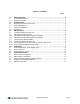
TABLE OF CONTENTS Page 1.0 1.1 1.2 2.0 2.1 2.2 2.3 2.4 3.0 3.1 3.2 3.2.1 3.2.2 3.3 3.3.1 3.3.2 3.3.3 4.0 4.1 4.2 4.3 5.0 5.1 5.2 5.3 5.4 6.0 SPECIFICATIONS .............................................................................................................. 2 Technical Specifications ..................................................................................................... 2 Ordering Information ............................................................................................
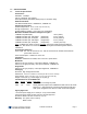
1.0 1.1. SPECIFICATIONS Technical Specifications Performance: Data Rate: 100 Mbps Half- or Full-Duplex, auto-sensing 800ns (80 bit-times) Path Delay Value (PDV) for conversion delay Network Standards: Fast Ethernet IEEE 802.
1.
or power strip. Each converter features a full set of LEDs that convey essential diagnostic and status information. See Section 4.1, LED Indicators, for specific LED function information. ProMedia-100 media converters are designed to provide low-temperature operation over an extended period to make them some of the most reliable in the industry.
3.0 INSTALLATION This section describes the installation of the ProMedia-100 media converters, including location, segment distance calculation and media connection. 3.1 Locating the Media Converter Unit The compact and lightweight design of the ProMedia-100 media converter allows it to be easily installed in most any location.
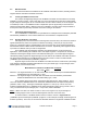
full-duplex media (15,000 m) [57/15,000 x 100% = 57%]. The length of twisted pair Segment Y is 12m (40 ft). This is 12% of the maximum allowable distance for 100BASE-TX full-duplex twisted-pair media (100 m) [12/100 x 100% = 12%]. The total of the two percentages (57% + 12%) is 69%, which is allowable. 3.2.2 Segment Distances, Half duplex Fast Ethernet shared bandwidth devices operate with multiple nodes in a traffic domain. When a node attempts to send a packet, it may hit another packet passing by, i.e.
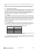
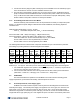
Table 3.4b: Worst case round-trip delay for Fast Ethernet device components* Component Round-trip delay in Bit Times (BT) 2 TX DTEs 100 2 FX DTEs 100 1 FX and 1 TX DTE 100 2 T4 DTEs 138 1 T4 and 1 TX or FX DTE 127 Class I Repeater 140 Class II Repeater with any 92 combination of TX and FX ports Class II Repeater with T4 ports 67 *Worst case delays taken from IEEE Std 802.3u-1995.
It is obvious that using twisted pair wiring to connect the hubs would enable the interconnect length to be the 100 meters maximum for twisted pair media, and this would still leave about a hundred BTs as a safety margin. In other words, use of ProMedia-100s and fiber in this case did not gain allowable maximum cable distance vs. TP cable without the ProMedia-100s. Consider a more typical use of ProMedia-100s in a shared Fast Ethernet segment.
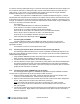
4. Connect the Receive (RX) port (dark colored post) on the ProMedia-100 to the Transmit (TX) port of the remote device. Use the non-color coded fiber strand for this. 5. The LINK LED corresponding to the fiber port, on the front of the product, will illuminate when a proper connection has been established at both ends (and when power is ON in the units at each end). If LINK is not lit after cable connection, the normal cause is improper cable polarity.
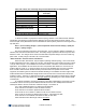
plug. Both types include a lightweight DC power cord to the applicable power jack on the media converter unit. 4.2 Front Panel LEDs Description LED PWR Illuminates GREEN to indicate the unit is receiving DC power. LINK (RJ45 port) Illuminates GREEN, to indicate proper connectivity on the 100BASE-TX network segment. LINK will turn off in the event connectivity is lost between the ends of the twisted pair segment or a loss of power occurs in the unit or remote device.
5.2 When Calling for Assistance Please be prepared to provide the following information: 1. A complete description of the problem, including the following points: a. The nature and duration of the problem. b. Situations when the problem occurs. c. The components involved in the problem. d. Any particular application that, when used, appears to create the problem 2. An accurate list of Waters Network Systems product model(s) involved. Include the date(s) that you purchased the products from your supplier.
Ship the package to: Waters Network Systems Attention: Customer Service 945 37th Avenue, NW Rochester, MN 55901 6.0 Warranty Information Waters Network Systems’ Warranty Statement Waters Network Systems’ products are warranted against defects in materials and workmanship. The warranty period for each product will be provided upon request at the time of purchase. Unless otherwise stated, the warranty period is for the useable life of the product.