
Installation guide

ProMedia-100 Manual Page 8
It is obvious that using twisted pair wiring to connect the hubs would enable the interconnect length to be
the 100 meters maximum for twisted pair media, and this would still leave about a hundred BTs as a
safety margin. In other words, use of ProMedia-100s and fiber in this case did not gain allowable
maximum cable distance vs. TP cable without the ProMedia-100s.
Consider a more typical use of ProMedia-100s in a shared Fast Ethernet segment. A stack of
Fast Ethernet hubs comprises the only repeater in the collision domain, and the users and servers in the
local workgroup are each connected via Category 5 twisted pair cable, a maximum of 30 meters (100 ft.)
in length. It is desired to connect one remote user with a fiber NIC via fiber cable, using a ProMedia-100
in the circuit. How long can the fiber cable be?
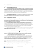
The solution is :
512 = total available Bit Times in a collision domain diameter,
minus 100 BT for two DTEs on each end leaves 412 BTs,
minus 90 BT for one Class II stackable repeater leaves 322 BTs,
minus 30 BT for one 30-meter TP cable from hub to user node leaves 292 BTs,
minus 5 BT for a short TP cable from the hub to -100 leaves 287 BTs,
minus 80 BT for one ProMedia-100 leaves 207 BTs for fiber cable,
which indicates a fiber cable length of about 200 meters
.
3.3 Connecting Ethernet Media
Connecting Ethernet media to the ProMedia-100 media converter is very simple and
straightforward. Using a properly terminated media segment, simply attach the cable end to the
appropriate connector.
See Sections 4.2 and 4.3 for a description of the LEDs.
3.3.1 Connecting Twisted Pair (RJ45, standard and Link Pass-through models)
The following procedure describes how to connect a 100BASE-TX twisted pair segment to the
RJ45 port on the ProMedia-100 media converters. The procedure is the same for both unshielded and
shielded twisted pair segments.
1. Using standard 100BASE-TX media, insert either end of the cable with an RJ45 plug into the
RJ45 connector of the ProMedia-100 media converter.
2. Connect the other end of the cable to the corresponding device.
3. Use the LINK LED to ensure proper connectivity by noting that the LED will be illuminated when
the units are powered and proper connections established. If the LINK LED is not illuminated,
change the setting of the up-link switch If this does not help, ensure that the cable is connected
properly at both ends and is not defective.
3.3.2 Connecting Fiber Optic 100BASE-FX, Type ST and SC
The following procedure applies to 100BASE-FX applications using the ProMedia-100 media
converter with ST-type (twist-lock) and SC-type (snap-in) fiber connectors.
1. Before connecting the fiber optic cable, remove the protective dust caps from the tips of the
connectors on the ProMedia-100. Save these dust caps for future use.
2. Wipe the ends of the dual connectors clean with a soft cloth or lint-free lens tissue dampened in
alcohol. Make certain the connectors are clean before connecting.
Note
: One strand of the duplex fiber optic cable is coded using color bands at regular
intervals; you must use the color-coded strand on the associated ports at each end of the
fiber optic segment.
3. Connect the Transmit (TX) port (light colored post) on the ProMedia-100 to the Receive (RX) port
of the remote device. Begin with the color-coded strand of the cable for this first “Transmit-to-
Receive” connection.