2 OPERATING MANUAL ProSwitch 2800M/MR Managed Modular Fiber and Copper Switch Chassis CORPORATE HEADQUATERS MANUFACTURING/CUSTOMER SERVICE 7401 Metro Blvd., Suite 560 Edina, MN 55439 Phone: 800.441.5319 Phone: 952.831.5603 Fax: 952.831.5605 945 37th Avenue, NW Rochester, MN 55901 Phone: 800.328.2275 Phone: 507.252.1951 Fax: 507.285.1952 Web site: http://www.watersnet.
TABLE OF CONTENTS 1.0 SPECIFICATIONS ........................................................................................................................... 4 2.0 PACKAGE CONTENTS................................................................................................................... 7 3.0 INTRODUCTION.............................................................................................................................. 7 3.1 3.2 3.3 3.4 3.5 3.6 3.6 3.7 3.8 3.9 3.10 3.11 3.11.1 3.
5.16 5.17 5.18 5.19 5.19.1 5.19.2 5.20 5.21 5.22 5.23 5.24 5.25 5.26 5.27 5.28 6.0 6.1 6.2 7.0 MAINTENANCE ........................................................................................................................... 142 7.1 8.0 EXAMPLES ........................................................................................................................ 142 TROUBLESHOOTING.................................................................................................................
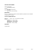
1.0 Specifications OPERATIONAL CHARACTERISTICS MAC Address Table: 8K Switching Mode: Store-and-forward Memory Buffer Size: 256Kb packet buffer 128Kb control buffer PERFORMANCE Non-blocking wire speed Auto negotiation Auto-MDIX Back pressure flow control for half duplex Flow control for full duplex Filtering/Forwarding Rate Performance 10Mbps: 14,880 pps 100Mbps: 148,800 pps 1000Mbps: 1,488,000 pps LED INDICATORS Per port: Power; Link/Activity; FDX; speed System LED Power NETWORK STANDARDS IEEE 802.
GVRP Port mirroring Port trunking Flow control Port security Static MAC address security TFTP software upgrade capability EMI/SAFETY COMPLIANCE FCC Class A & CE Mark Approval CABLE CONNECTORS Copper: RJ45 shielded female ports 10/100Mbps: CAT5 UTP or better Console Port: RS232 Cable/DB9 connector Fiber: MM FX port: 50/125um, 62.5/125mm SM FX port: 9/125um MM SX port: 50/125um, 62.
OPERATING ENVIRONMENT Ambient Temperature: 32° to 104°F (0° to 40°C) Storage: -68° to 158°F (20° to 70°C) Ambient Humidity: 32% to 104% (non-condensing) MECHANICAL Enclosure: Rugged high-strength sheet metal suitable for stand alone or rack mountable Cooling Method: Fan cooled PHYSICAL CHARACTERISTICS Dimensions: 17.4 W x 11 D x 1.75” H (442 x 281 x 44mm) Weight: 2800M Chassis: 7.5 lbs (3.4 kg) 2800MR Chassis: 10 lbs (4.6 kg) Copper Module: .61 lbs (.28 kg) Fiber Module: .75 lbs (3.
2.0 Package Contents Examine the shipping container for obvious damage prior to installing this product. Notify the carrier of any damage that you believe occurred during shipment. Ensure that the items listed below are included. If an item is missing, please contact your supplier. 3.
Supports a snapshot of the system Information upon login Port mirror function Static trunk function Supports 802.
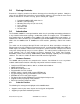
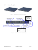
3.5 Hardware Description Figure 3.1 - 2800M Switches with Copper and Fiber Modules Fiber Port Status: Link LEDSET Button LEDSET button is used to change the LED display mode Power Indication LED Gigabit Dual Media Port: SFP/TP Fast Ethernet Port Fiber Port Status: ACT/FDX/SPD LED SET Mode: ACT/FDX/SPD RESET Button: RESET button is used to reset the management system. Figure 3.
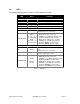
3.6 LEDs The following table provides the status and description of the LEDs: LED CPURUN POWER ACT FDX SPD Color System LED Green Green Green Green Green Function Blinks when CPU is on and good Switch is receiving power Lit when LEDSET set on active mode Lit when LEDSET set on full-duplex mode Lit when LEDSET set on speed mode 10/100Mbps Ethernet Port 1 to 8 of 3 Module LED Port has established a valid link LNK Green Off when there is no connection a.
3.7 Rear Panel Located on the rear panel is the RS-232 DB-9 interface which is used for switch management configuration. AC Line 100-240V 50/60 Hz RS-232 DB-9 Connector Figure 3.4 - Rear View of 2800M 3.8 Installation Choose a surface for your switch that is clean, smooth and near a power outlet. Make sure that there is enough clearance around the switch to allow attachment of cables, power cord and air circulation. 1. Plug in the power cord into the switch. 2.
3.11.1 Cabling Requirements for SFP Module The GSM2800M has four slots for SFP modules. These slots provide fiber connectivity for Gigabit Ethernet and are optional. The switch supports both multimode and singlemode fiber connectivity. The following table lists the types of fiber that are supported by the GSM2800M/MR. Multimode Fiber Cable and Modal Bandwidth Multimode 62.5/125µm IEEE 802.
the Level 1 switch. This generally applies if no VLAN or other special requirements are applied. Example 1: All switch ports are in the same local area network. each other (See Figure 3.4). All ports can access Figure 3.4 - No VLAN Configuration Diagram If VLAN is enabled and configured, each node in the network that can communicate with each other directly is contained in the same VLAN area. In Example 2, the VLAN area is defined by the configured VLAN.
3. The switch at one switch. manager has to assign different names for each VLAN group Case 2b: Port-based VLAN (See Figure 3.6) Figure 3.6 - Port-based VLAN Diagram This is an example of how VLANs can be set up between two switches. 1. VLAN1 members cannot access VLAN2, VLAN3 and VLAN4 members. 2. VLAN2 members cannot access VLAN1 and VLAN3 members, but they can access VLAN4 members. 3. VLAN3 members cannot access VLAN1, VLAN2 and VLAN4. 4.
Figure 3.7 - Attribute-based VLAN Diagram 4.0 Access to Management Functions There are three ways to access switch management functions: 1. RS-232 serial port connection (CLI) 2. Telnet 3. Web Note: Before accessing management functions through Telnet or the Web, you must modify the IP address, subnet mask, default gateway and DNS through the RS-232 connection. 4.1 Using the RS-232 Serial Port Connection To configure the switch via the RS-232 serial port connection, follow these steps: 1.
4.2 Configuring IP, Subnet Mask and Default Gateway The default settings for your switch are listed in the following table: Default Value IP Address Subnet Default Gateway GSM2800M/MR 192.168.1.1 255.255.255.0 192.168.1.254 Table 4-1 You may either change the IP address of the switch or change the IP address of your workstation. To change the IP address of the switch, via the console connection, you will have to use the CLI command listed below. A complete list of CLI commands is in Section 6.
Before you are able to communicate with the switch, you must know the IP address of the switch. The default IP setting for the 2800M is: IP = 192.168.1.100 Subnet Mask = 255.255.255.0 Default Gateway = 192.168.1.253 Once you know the IP address, follow these instructions: 1. Connect the switch with a UTP cable to your workstations. Note: If the workstation connects to the switch, you will have to setup the same subnet mask between them. 2. Access your web browser or use the console connection.
network identifier identifies the network on which the host resides, while the host identifier identifies the particular host on the given network. The host identifier must be unique in the same LAN. Each class has its own network range between the network identifier and host identifier in the 32 bits address. IP address is known as IPv4. 32 bits Network identifier Host identifier With “classful” addressing, the IP address is divided into three classes: class A, class B and class C.
Class C: IP address range between 192.0.0.0 and 223.255.255.255. Each class C network has a 24-bit network prefix followed 8-bit host address. There are 2,097,152 (2^21)/24 networks able to be defined with a maximum of 254 (2^8 –2) hosts per network. Bit # 0 1 2 3 23 24 31 110 Network address Host Class D and E: Class D is a class with first 4 MSB (most significance bit) set to 1-1-1-0 and is used for IP Multicast. See also RFC 1112.
128.1.2.128/25 Network Subne 10000000.00000001.00000010.1 0000000 25 bits All 0s = 128.1.2.128 1 0000000 1 1111111 All 1s= 128.1.2.255 In this diagram, the subnet mask with 25-bit long, 255.255.255.128, contains 126 members in the sub-netted network. The length of network prefix equals the number of the bit with 1s in that subnet mask. With this, you can easily count the number of IP addresses matched. The following table shows the result. Prefix Length No. of IP matched No.
According to the scheme above, a subnet mask 255.255.255.0 will partition a network with the class C. This means there will be a maximum of 254 effective nodes existing in this sub-netted network and is considered a physical network in an autonomous network. It owns a network IP address which may look like 168.1.2.0. With the subnet mask, a bigger network can be divided into smaller pieces. If you want to have more than two independent networks in a LAN, the network must be partitioned.
DNS: The Domain Name Server translates the human readable machine name to IP address. Every machine on the Internet has a unique IP address. A server generally has a static IP address. To connect to a server, the client needs to know the IP of the server. However, generally the name is used to connect to the server. Thus, the switch DNS client program (such as a browser) will ask the DNS to resolve the IP address of the named server. 5.
Figure 5.1 – Login Screen 5.1 Overview of Web Management Once you have logged into the switch, the opening screen displays the System Information. On the left side of the screen, the function tree for all of the management functions is displayed. We will explore these functions in this chapter.
Figure 5.2 – System Information The top of the screen displays the front panel of the switch. The linked ports will be displayed in green and the ports that are not connected will be dark. The optional modules will display a cover plate if no module exists and will show a module if a module is present. The image of module depends on the installed module. If the module port is not connected, the port be dark and, if linked, green.
Figure 5.3 – Port Detail Information Figure 5.3 shows basic information of the selected port. You will be able to view port status, traffic status and bandwidth rating for egress and ingress respectively. On the left-top corner, there is a pull-down list for Auto Logout. For additional switch security, an auto-logout function is available to protect you from illegal users if you don’t logout of the management functions when you are finished. The Auto Logout default is set to three minutes.
The following list is the full function tree for web user interface. Root System Port SNMP DNCP Boot IGMP Snooping VLAN MAC Table GVRP STP Trunk 802.
5.2 System Information Function name: System Information Function description: Show the basic system information. Parameter description: Model name: The model name of this device. System description: Describes the device. “3 Slot, 24 FE + 2 GbE Dual Media L2 Managed Switch”. Location: The location where this switch is being used. User-defined. Contact: For the purpose of managing and maintaining the device, enter the contact person and phone to be used for help.
It is the Ethernet MAC address of the management agent in this switch. Device Port: Show all types and numbers of the port in the switch. RAM size: The size of the DRAM in this switch. Flash size: The size of the flash memory in this switch. 5.3 IP Configuration IP configuration is one of the most important configurations in the switch. Without the proper setting, the network manager will not be able to manage or view the device.
IP address from DHCP server, the device will stop the booting process. If the field is set to “Disable”, you will have to input the IP address manually. For more details about IP address and DHCP, refer to Section 4.4 - IP Address Assignment. Default: Disabled IP address: Users can configure the IP settings and enter new values if the DHCP function is set to Disable. Click the Apply button to update. When DHCP is disabled, the default is 192.168.1.1.
DHCP is enabled. DNS can help you easily remember the mnemonic address name with the meaningful words in it. No assignment of DNS address is made by default. Default: 0.0.0.0 5.4 Time Configuration The switch provides a manual and automatic method to set the system time via NTP. Manual setting is simple. Input “Year”, “Month”, “Day”, “Hour”, “Minute” and “Second” within the valid value range indicated in each item.
of hours, according to the starting date and the ending date. For example, if you set the daylight saving to be one hour, when the time passes over the starting time, the system time will be increased one hour after one minute at the time since it passed over. And when the time passes over the ending time, the system time will be decreased one hour after one minute at the time since it passed over. The switch supports valid configurable daylight saving time is –5 ~ +5 step one hour.
Figure 5.5 – System Time Setting 5.5 Account Configuration Only the administrator can create, modify or delete the username and password. The administrator can modify passwords without confirming the password. Guest users can modify their own password. Only one administrator is allowed to exist and unable to be deleted. Up to four guest accounts can be created.
Figure 5.6 – Account Configuration 5.6 Management Policy Through the management security configuration, the manager can perform the setup to control the switch and limit user to access the switch. The following rules are provided for the management of the switch: Rule 1: If no lists exists, all connections are accepted. Accept __________________________________________________ Rule 2: If “accept lists” exists, all connections will be denied except the connection inside the accepting range.
Accept Accept Deny Deny| Acc | Deny | Acc | Deny __________________________________________________ Function name: Management Security Configuration Function description: The switch provides a Management Security Configuration function. With this function, the manager can easily control the mode that the is used to connect to the switch.
IP Range: The switch supports two kinds of options for managed valid IP Range, including Any and Custom. Default is Any. Custom allows you to assign an effective IP range. The valid range is 0.0.0.0~255.255.255.255. Incoming Port: The switch supports two kinds of options for managed valid Port Range, including Any and Custom. The default is Any. Custom allows you select the ports that should be used and the ports that should be restricted in the management security configuration.
The device of the group will be shown as the station address (the last number of IP Address) + device name on the button (e.g. 196_CES2326B). If no corresponding device exists, it will show ”---“. Once the devices join the group successfully, they can be managed via Master device, and users will not be able to manage them via telnet/console/web individually. Up to 16 devices can be grouped for VSM; however, only one Master is allowed to exist in each group.
Figure 5.9 – Virtual Stack Configuration 5.
5.8.1 Port Status The port status function gathers the current status for all ports. The information is displayed by the order of port number, link status, port state, auto-negotiation status, speed/duplex and flow control. If a fiber module is installed in one or both of the slots, the current status for those ports will be displayed. See Figure 5.10 Figure 5.10 – Current Port Status Function name: Port Status Function Description: Port status reports the current status of all ports in the switch.
Displays an active or inactive port. If the link is connected to a working device, the link will show that is it Up; otherwise, it will show Down. This is determined by the hardware on both devices of the connection. No default value. State: Displays the communication function of the port is Enabled or Disabled. When it is enabled, traffic can be transmitted and received via this port. When it is disabled, no traffic can be transferred through this port. Port State is configured by user. Default: Enabled.
Figure 5.11 – Port Detail Parameter description of Port 25 and Port 26: Connector Type: Displays connector type (UTP, SC, ST, LC, etc.) Fiber Type: Display the fiber mode (multi or singlemode) Tx Central Wavelength: Displays the fiber optical transmitting central wavelength (850nm, 1310nm, 1550nm, etc.) Baud Rate: Displays the maximum baud rate of the fiber module supported, for instance (10M, 100M, 1G, etc.) Vendor OUI: Displays the Manufacturer's OUI code which is assigned by IEEE.
Temperature: Displays the current temperature of the SFP module. Vcc: Displays the working DC voltage of SFP module. Mon1(Bias) mA: Displays the Bias the installed SFP module. Mon2(TX PWR): Displays the transmit power of SFP module. Mon3(RX PWR): Displays the receiver power of SFP module. Figure 5.12 – Slot Detail Information Parameter description of slots 1-3: Serial number: The serial number is assigned by the manufacturer. Hardware-Mechanical version: The version of Hardware and Mechanical.
Displays the fiber mode, multi or singlemode. Fiber Cable (for fiber module only): Displays the cable type, Two Wires, Single Wire. Wavelength (for fiber module only): Displays the wavelength of the light transmitted in the fiber ( 850nm, 1310nm). Distance (for fiber module only): Displays the maximum distance the port supports (100m, 10km, 20km, etc). Speed (for fiber module only): Displays the maximum speed of the port, 1G or 100M. 5.8.
traffic can pass even if it linked up. Default: Enable. Speed/Duplex: Set the speed and duplex of the port. In speed, 10/100Mbps baud rate is available for Fast Ethernet, Gigabit module in port 25, 26. If the media is 1Gbps fiber, it is always 1000Mbps and the duplex is full only. If the media is TP, the Speed/Duplex is comprised of the combination of speed mode, 10/100/1000Mbps, and duplex mode, full duplex and half duplex. The following table summarized the function the media supports.
The number of the packets received. Tx Packet: The number of the packets transmitted. Tx Packet: The number of the packets received. Tx Collision: Number of collisions. Rx Error Packet: Number of bad packets received. Figure 5.14 – Simple Counter 5.8.4 Detail Counter The function of the Detail Counter is to collect information and provide the counting for the traffic of the port, whether the packet is good or bad. In Figure 5.14, the counter is displayed one port at a time.
Figure 5.15 – Detail Counter Each data field is 20-digits. If the counting overflows, the counter will be reset and counting will be restarted. The data is updated based on the time interval defined by the user. The valid range is three to ten seconds. The refresh interval is used to set the update frequency. Default update time is three seconds. Function name: Detail Counter Function description: Displays the detailed number of each port’s traffic. In Figure 5.
Rx Unicast Packets: Displays the number of received unicast packets Rx Broadcast Packets: Displays the number of received broadcast packets. Rx Multicast Packets: Displays the number of received multicast packets. Rx Pause Packets: Displays the number of received pause packets. Tx Collisions: Number of collisions from transmitting frames. Tx Single Collision: Number of frames transmitted that experienced exactly one collision.
Packets 512-1023 Octets: Number of 512 ~ 1023-byte frames from good and bad packets received. Packets 1024- 1522 Octets: Number of 1024-1522-byte frames from good and bad packets received. Tx Packets: The number of packets transmitted. TX Octets: Total transmitted bytes. Tx Unicast Packets: Displays the number of transmitted unicast packets. Tx Broadcast Packets: Displays the number of transmitted broadcast packets. Tx Multicast Packets: Displays the number of transmitted multicast packets.
5.9 SNMP Configuration Any Network Management System (NMS) running the Simple Network Management Protocol (SNMP) can manage devices equipped with the SNMP agent, provided that the Management Information Base (MIB) is installed correctly on the managed devices. SNMP is a protocol that is used to govern the transfer of information between SNMP manager and agent. This protocol traverses the Object Identity (OID) of the management Information Base (MIB), described in the form of SMI syntax.
Trap: There are six trap hosts supported. Each of them has its own community name and IP address and is user-definable. To set up a trap host means to create a trap manager by assigning an IP address to host the trap message. In other words, the trap host is a network management unit with SNMP manager receiving the trap message from the managed switch with SNMP agent issuing the trap message. Six trap hosts can prevent the important trap messages from being lost.
Figure 5.17 – DHCP Boot 5.11 IGMP Snooping IGMP snooping is used to establish the multicast groups to forward multicast packets to member ports. IGMP snooping avoids wasting the bandwidth while IP multicast packets are running over the network. A switch that does not support IGMP snooping cannot tell a multicast packet from broadcast packet, so it treats them as broadcast packets. Without IGMP snooping, the multicast packet forwarding function is no different from broadcast packets.
Figure 5.18 – IGMP Snooping Configuration Function name: IGMP Snooping Status Function description: IGMP is used to snoop the status of IP multicast groups and display its associated information in both tagged VLAN and non-tagged VLAN networks. By enabling IGMP, you can monitor the IGMP snooping information, which contains the multicast member list with the multicast groups, VID and member port.
Displays VLAN ID for each multicast group. Member Port: Displays member ports that join each multicast group. Function name: Allowed Group Function description: The Allowed Group function allows IGMP Snooping to set up the IP multicast table based on user’s specific conditions. IGMP report packets that meet the items you set up will be joined or form the multicast group. Figure 5.
Add: A new entry of allowed group configurations can be created after the parameters as mentioned above had been setup by choosing Add. Edit: The entry also can be modified by choosing Edit. Delete: The entry of allowed group configuration can be removed from the allowed group. 5.12 VLANs The switch supports Tag-based VLAN (802.1q) and Port-based VLANs. 256 active VLANs are supported and VLAN ID can range from 1~4094.
Symmetric VLAN: Symmetric VLAN follows an Ingress Rule (Rule 1, The Ingress Filtering Rule 1 is “forward only packets with VID matching this port’s configured VID”.). For example, if port 1 receives a tagged packet with VID=100 (VLAN name=VLAN100), and if Symmetric-VLAN function is enabled, the switch will check to see if port 1 is a member of VLAN100. If it is, the received packet is forwarded; otherwise, the received packet is dropped.
Function description: Displays the information of existing Tag-based VLAN Groups. You can also easily create, edit and delete a Tag-based VLAN group by choosing the Add, Edit or Delete functions. Users can add a new VLAN group by inputting a new VLAN name and VLAN ID after choosing Add. Parameter description: VLAN Name: The name defined by administrator is associated with a VLAN group. Valid letters are A-Z, a-z, 0-9, “-“, and “_” characters. The maximal length is 15 characters. VID: VLAN identifier.
Add Group: Input the VLAN name, VID and then choose the member by clicking the check box beside the port No. to create a new Tag-based VLAN. The parameter of Untag stands for an egress rule of the port. If you check box beside the port No., outgoing packets with this VID from this port will be untagged. Choose Apply save the setting. Figure 5.22 – Tag-based VLAN Delete Group: Choose Delete to remove the selected group entry from the Tag-based group table. Figure 5.
Select a group entry and choose Edit to modify a group’s description, member and untag settings. 5.12.3 PVID Function name: PVID Function description: In PVID Setting, user can input VID number to each port. The range of VID number is from 1 to 4094. You can also can choose ingress filtering rule (Rule 2) to each port. The Ingress Filtering Rule 2 is “drop untagged frames”. While Rule 2 is enabled, the port will discard all Untagged-frames. Figure 5.
Drop Untag: Drop untagged frame. You can configure a given port to accept all frames (Tagged and Untagged) or just receive tagged frames. If the former is the case, then the packets with tagged or untagged will be processed. If the later is the case, only the packets carrying VLAN tag will be processed and the rest packets will be discarded. 5.12.4 Port-based Group Function name: Port-based Group Configuration Function description: Displays the information of the existing Port-based VLAN Groups.
Add Group: Create a new Port-based VLAN. Input the VLAN name and choose the member by clicking the check box beside the port No. Choose Apply save the setting. Figure 5.26 – Port-based VLAN Delete Group: Choose Delete to remove the selected group entry from the Port-based group table. Figure 5.27 – Port-based Group Edit a group: Select a group entry and press Edit to modify a group‘s description and member set.
Select a group entry and select Edit. This allows you to modify the group’s setting. 5.13 MAC Table MAC Table Configuration includes the following functions: MAC Table Information MAC Table Maintenance Static Forward Static Filter MAC Alias Function name: MAC Table Information Function Description: Displays the static or dynamic learning MAC entry and the state for the selected port. Parameter description: Port: Select the desired port.
The MAC address of the searched entry. Port: The port that exists in the searched MAC Entry. VID: VLAN Group that MAC Entry exists. State: Display the method that this MAC Entry is built. It may show Dynamic MAC or Static MAC. Figure 5.28 – MAC Table Information Function Name: MAC Table Maintenance Function Description: This function allows the user to set up the processing mechanism of MAC Table. An idle MAC address exceeding MAC Address Age-out Time will be removed from the MAC Table.
to these two ports. This value cannot be configured. Figure 5.29 – MAC Maintenance Function Name: Static Setting Function Description: The function of Static is used to configure MAC’s manners inside of the switch. Three kinds of manners are included in this function: static, static with destination drop and static with source drop. When static is chosen, assign a MAC address to a specific port. All of the switch’s traffics sent to this MAC address will be forwarded to this port.
Figure 5.30 – Static MAC Parameter description: MAC: MAC is six-byte long Ethernet hardware address and usually expressed by hex and separated by hyphens. For example, 00 – 19 – B6 – C5 – 00 – 01 VID: VLAN identifier. This will be filled only when tagged VLAN is applied. Valid range is 1 ~ 4094. Queue: Set up the priority (0~3) for the MAC. Forwarding Rule: Static: A MAC address is assigned to a specific port. All of the switch’s traffics sent to this MAC address will be forwarded to this port.
Function name: MAC Alias Function description: MAC Alias function is used to let you assign a MAC address a plain English name. This will help you tell which MAC address belongs to which user in the illegal access report. At the initial time, it shows all pairs of the existed alias name and MAC address. There are three MAC alias functions in this function folder, including MAC Alias Add, MAC Alias Edit and MAC Alias Delete.
Parameter description: MAC Address: MAC address is a six-byte long Ethernet hardware address and usually expressed by hex and separated by hyphens. For example, 00 – 19 – B6 – C5 – 00 – 02 Alias: MAC alias name you assign. Note: If there are too many MAC addresses learned in the table, we recommend you input the MAC address and alias name directly. 5.
The function of GVRP Config is used to configure each port’s GVRP operation mode. There are seven parameters to be configured which are described below. Parameter description: GVRP State Setting: This function allows you to enable or disable the GVRP function. Use the drop down list and select the Downward arrow key to choose Enable or Disable. Select Apply and the function will take effect immediately. Join Time: Used to declare the Join Time in unit of centisecond.
Disabled: In this mode, the switch dynamic VLAN will be created when this port received GVRP PDU. The default setting is Normal. Enabled: In this mode, the switch does not create dynamic VLAN when this port received GVRP PDU. Except received dynamic VLAN message of the GVRP PDU is an existed static VLAN in the switch. This port will be added into the static VLAN members dynamically.
JoinIn Message Packets: Number of GARP BPDU with Join In message received by the GARP application. LeaveEmpty Message Packets: Number of GARP BPDU with Leave Empty message received by the GARP application. Empty Message Packets: Number of GARP BPDU with Empty message received by the GARP application. Transmitted: Total GVRP Packets: Total GARP BPDU transmitted by the GVRP application. Invalid GVRP Packets: Number of invalid GARP BPDU transmitted by the GVRP application.
Refresh: Refresh function allows you to see current GVRP group status. Figure 5.34– GVRP Group Information 5.15 Spanning Tree Configuration (STP) Configuration The Spanning Tree Protocol (STP) is a standardized method (IEEE 802.1D) used to avoid loops in switched networks. When STP is enabled, only one path is active between any two nodes on the network at a time. Once Spanning Tree Protocol has been enabled, advanced functions can be configured.
Designated Root: Displays the root bridge ID of this network segment. If this switch is a root bridge, the Designated Root will show this switch’s bridge ID. Designated Priority: Displays the current root bridge priority. Root Port: Displays port number connected to root bridge with the lowest path cost. Root Path Cost: Displays the path cost between the root port and the designated port of the root bridge. Current Max. Age: Displays the current root bridge maximum age time.
Figure 5.35 – STP Status 5.15.2 Configuration STP includes Rapid Spanning Tree Protocol (RSTP). STP has six parameters to be configured. These parameters are described below. Function name: STP Configuration Function description: Set the following Spanning Tree parameters to control STP function (enable/disable). Select mode RSTP/STP and affect STP state machine behavior to send BPDU in the switch. The default setting of STP is Disable. Parameter description: Spanning Tree Protocol: Set 802.
When the GSM switch is the root bridge, the whole LAN will apply the number set by the switch as their maximum age time. When a bridge received a BPDU originating from the root bridge and if the message age conveyed in the BPDU exceeds the Max. Age of the root bridge, the bridge will treat the root bridge as malfunctioning and issue a Topology Change Notification (TCN) BPDU to all other bridges. All bridges in the LAN will re-calculate to determine who the root bridge is. The valid value of Max.
5.15.3 STP Port Configuration Function name: STP Port Setting Function description: In the STP Port Setting, one item selection and five parameters are available for setup. You can disable and enable each port. You can set Path Cost and Priority for each port and set Admin Edge Port and Admin Point To Point. Parameter description: Port Status: Displays the current state of a port for viewing only. According to the 802.1w specification, there are three possible states.
Default is 128. Admin Edge Port: If you select Yes, this port will be an edge port. An Edge Port is a port connected to a device that knows nothing about STP or RSTP. Usually, the connected device is an end station. Edge Ports will immediately transit to forwarding state and skip the listening and learning state because the edge ports cannot create bridging loops in the network. This will expedite the convergence. When the link on the edge port toggles, the STP topology keeps unchanged.
5.16 Trunking Configuration The Port Trunking Configuration is used to configure the settings of Link Aggregation. More than one port can be bundled with the same speed, full duplex and the same MAC to be a single logical port. The logical port aggregates the bandwidth of these ports. This means you can apply your current Ethernet equipment to build the bandwidth aggregation.
Function name: Port Setting/Status Function description: Port setting/status is used to configure the trunk property of each and every port in the switch system. Parameter description: Method: This determines the method a port uses to aggregate with other ports. None: A port does not aggregate with other ports. LACP: A port uses LACP as its trunk method to aggregate with other ports also using LACP. Static: A port uses Static Trunk as its trunk method to aggregate with other ports also using Static Trunk.
Status: This field represents the trunking status of a port which uses a trunking method other than “None”. It also represents the management link status of a port which uses the “None” trunking method. “---“ means “not ready” Figure 5.38 – Trunk Port Setting Status Function name: Aggregator View Function description: To display the current port trunking information from the aggregator point of view. Parameter description: Aggregator: Displays the aggregator ID (from 1 to 26) of every port.
Figure 5.39 – Aggregator View Function name: LACP Detail (LACP Aggregator Detailed Information) Function description: Displays the detailed information of the LACP trunking group. Parameter description: Actor: The switch you are using to view LACP. Partner: The peer system from the aggregator’s view. System Priority: Displays the System Priority of a system ID. MAC Address: Displays the MAC Address of a system ID. Port: Displays the port number of an LACP port ID.
Figure 5.40 – LACP System Priority Function name: LACP System Priority Function description: Used to set the priority of the LACP system ID. LACP will only aggregate together the ports whose peer link partners are all on a single system. Each system supports LACP will be assigned a globally unique System Identifier for this purpose. A system ID is a 64-bit field comprising a 48-bit MAC Address and 16-bit priority value. Parameter description: System Priority: The System Priority can be set by the user.
Before the devices or workstations can access the network resources through the ports under 802.1X control, the devices or workstations must send an authentication request to the authenticator. The authenticator passes the request to the authentication server to authenticate and verify, and the server informs the authenticator to grant the request for authorization for the ports. According to IEEE 802.
Authentication Server’s System Authenticator’s System Supplicant’s System Services Offered by Authenticator (e.g Bridge Relay) Supplicant PAE Controlled port Authenticator PAE Authentication Server Uncontrolled port Port Authorize MAC Enable LAN Figure 5.41 Figure 5.42 represents a typical configuration; a single supplicant, an authenticator and an authentication server.
2. Either authenticator or supplicant can initiate the message exchange. If supplicant initiates the process, it sends EAPOL-start packet to the authenticator PAE and authenticator will immediately respond EAP-Request/Identity packet. 3. The authenticator periodically sends EAP-Request/Identity to the supplicant to request the identity it wants to be authenticated. 4.
Bridge LAN PC Radius Server Port connect Access blocked EAPOL-Start EAPOL EAP Radius Authenticator EAP-Request/Identity Radius-Access-Request EAP-Response/Identity Radius-Access-Challenge EAP-Request Radius-Access-Request EAP-Response (cred) Radius-Access-Accept EAP-Success EAP-Failure EAP-Logoff Access allowed Figure 5.43 – 802.1x Authentication The type of authentication supported in the switch is multihost 802.1x.
Function name: 802.1X State Setting Function description: This function is used to configure the global parameters for RADIUS authentication in 802.1X port security application. Parameter description: Radius Server: RADIUS server IP address for authentication. Default: 192.168.1.1 Port number: The port number to communicate with RADIUS server for the authentication service. The valid value ranges 1-65535. Default port number is 1812.
Indicate which port is selected to configure the 802.1X operation mode. Mode: 802.1X operation mode. There are three options, including Disable, Normal and Advanced. Default is Disable. Disable The chosen port acts as a plain port, which means 802.1X port access control does not work on the port. 802.1X with multihost In multihost mode, the devices connected to this port can access the network, once a supplicant is authorized. Figure 5.45 – 802.
802.1X with Multihost mode: With the function 802.1X Port Mode Configuration, devices can access the network through this port once the authenticator is authorized. The Port Status will display the following screen. If the port is granted to access the network, the port status is authorized, otherwise, unauthorized. Port Status: The current 802.1X status of the port. In Disable mode, this field is Disabled. Status: The current 802.1X status of the port. Figure 5.46 – 802.
ForceAuthorized: The controlled port remains in the authorized state. Auto: The controlled port is set to be in authorized state or unauthorized state depends on the result of the authentication exchange between the authentication server and the supplicant. Default: Auto reAuthMax (1-10): The number of authentication attempts that is permitted before the port becomes unauthorized. Default: 2 txPeriod (1-65535 s): A time period to transmitted EAPOL PDU between the authenticator and the supplicant.
Figure 5.47 – Port Parameter Setting 5.18 Alarm Configuration Alarm Configuration Events Configuration Email/SMS Configuration Function name: Events Configuration Function description: The Trap Events Configuration function is used to enable the switch to send out trap information while pre-defined trap events occur. The switch provides 23 different trap events. The trap information can be sent out in three ways, including email, mobile phone SMS (short message system) and trap.
Figure 5.48 – Trap Events Configuration Function name: Email/SMS Configuration Function description: Alarm configuration is used to configure the recipients of the alarm message via email or SMS, or both. The method is dependent on the settings. An email address or a mobile phone number has to be set in the alarm configuration (See Figure 5.49). If set properly, you can read the trap information from your email or mobile phone.
Mobile Phone 1-6: Additional mobile phone numbers that would like to receive the alarm message. Figure 5.49 – Alarm Configuration 5.19 Configuration The switch supports three copies of configurations, including the default configuration, working configuration and user configuration for your configuration management. The three copies are described below: Note: If you make changes to the configuration, you must save the configuration before rebooting the switch.
Figure 5.
5.19.1 Save/Restore Function name: Save As Start Configuration Function description: Save the current configuration as a start configuration file in flash memory. Figure 5.51 – Configuration Screen Function name: Save As User Configuration Function description: Save the current configuration as a user configuration file in flash memory. Figure 5.
Function name: Restore Default Configuration (includes default IP address) Function description: Restore Default Configuration function can retrieve the factory setting to replace the start configuration. If the factory settings are restored, the IP address of the switch will be restored to 192.168.1.1. Figure 5.
Function name: Restore User Configuration Function description: Restore User Configuration function retrieves the previous confirmed working configuration stored in the flash memory to update start configuration. When restoring the configuration, the system’s start configuration is updated and will be changed its system settings after rebooting the system. Figure 5.55 – Restore User Configuration 5.19.
Figure 5.56– Restore User Configuration 5.20 Security Function name: Mirror Configuration Function description: The Mirror Configuration is used to monitor the traffic of the network. For example, Port A and Port B are Monitoring Port and Monitored Port respectively, thus, the traffic received by Port B will be copied to Port A for monitoring. Parameter description: Mode: Used for the activation or de-activation of Port Mirror function. Default is disable.
Figure 5.57 – Mirror Configuration Function name: Isolated Group Function description: The Isolated Group function allows the port to be independent of other ports in the Isolated group,. Communication is not possible between these ports. But, the ports of the Isolated group are still able to communicate with the ports of the non-Isolated group. With this design, you can find and resolve looping problems on the network.
Figure 5.58 – Isolated Group Function name: Restricted Group Function description: The function of the Restricted Group is to decide the direction of transmitting packets for the specific port. The packets received by the port with the “Ingress” mode of Restricted Group will be sent to the ports with the “Egress” mode of Restricted Group. Parameter description: Mode: Used for the activation or de-activation of Restricted Group function. Default is disable.
Figure 5.59 – Restricted Group 5.21 Bandwidth Management Function name: Ingress Bandwidth Setting Function description: Ingress Bandwidth Setting function is used to set the limit of Ingress bandwidth for each port. Figure 5.
Parameter description: Port No.: Choose the port number. Valid ports are 1~26. Rate: Rate is used to set the limit of Ingress bandwidth for the port. Incoming traffic will be discarded if the rate exceeds the value you set up in Data Rate field. Pause frames are also generated if flow control is enabled. The format of the packets are limited to unicast, broadcast and multicast. Port 1~24 port numbers range from 66~102400. Port 25~26 port numbers ranges from 66~1024000 with the minimum unit of 1.
Function name: Storm Setting Function description: The bandwidth storm function is used to set up the limit of Ingress and Egress bandwidth for each port. Figure 5.62 – Bandwidth Storm Control Parameter description: Storm Type: Disable: Disable the function of the bandwidth storm control. Broadcast Storm Control: Enable the function of bandwidth storm control for broadcast packets. Multicast Storm Control: Enable the function of bandwidth storm control for multicast packets.
5.22 QoS (Quality of Service) Configuration The switch supports the following five QoS functions: MAC Priority 802.1p Priority IP TOS Priority DiffServ DSCP Priority Port Based Priority (VIP Port) Packets in the VIP Port will have highest transmitting priority. MAC Priority act on the destination address of MAC in packets. VLAN tagged priority field is affected by the 802.1p Priority setting. IP TOS Priority affects TOS fields of IP header.
The QoS functions as we mentioned above can be enabled at the same time. But, the following precedence will decide whether these functions work or not. enable both VIP and TOS o Choose priorities of VIP and TOS. enable both VIP and DSCP o Choose priorities of VIP and DSCP. enable both TOS and DSCP o Choose "DSCP". enable both VIP and DSCP o Choose priorities of VIP and DSCP. enable both 802.1p and TOS o Choose "TOS". enable both 802.1p and DSCP o Choose "DSCP". enable both 802.
Figure 5.63 – QoS Global Setting Function name: VIP Port Setting Function description: When the port is set as VIP Port, the packets enter this port and will have highest transmitting priority. For example, as you choose port 2 is VIP Port, simultaneously transmit packets from port 2 and port 3 to port 3 at speed of 100MB and let congestion happen. The packets for port 3 will be dropped because the packets from port 2 own highest precedence.
Figure 5.
Function name: 802.1p Setting Function description: This function will affect the priority of the VLAN tag. Based on priority of VLAN tag, it can handle up to eight priorities. Priorities can map to four queues (queue 0~3) and possess different bandwidth distribution according to your weight setting. Parameter description: 802.1p Priority Mapping: Each Priority can select Queue 0 ~ Queue 3.
Function name: D-Type TOS Function description: IP TOS Priority affects the TOS fields of the IP header It has an 8-bit SERVICE TYPE field that specifies how the datagram should be handled. The field could be divided into the following subfields. PRECEDENCE (3 bits), D-Type (Delay Priority, 1 bit) T-Type (Throughput Priority, 1bit) R-Type (Reliability Priority, 1 bit) M-Type (Monetary Cost Priority, 1 bit) UNUSED.
Figure 5.66 – TOS Delay Mapping Function name: T-Type TOS Function description: IP TOS Priority affects the TOS fields of the IP header. It has an 8-bit SERVICE TYPE field that specifies how the datagram should be handled. The field could be divided into the following six subfields: PRECEDENCE (3 bits) D-Type (Delay Priority, 1 bit) T-Type (Throughput Priority, 1 bit) R-Type (Reliability Priority, 1 bit) M-Type (Monetary Cost Priority, 1 bit) UNUSED.
TOS Throughput Priority Mapping: Each Priority can select Queue 0 ~ Queue 3. By Default, Priority 0 is mapped to Queue 0, Priority 1 is mapped to Queue 0, Priority 2 is mapped to Queue 1, Priority 3 is mapped to Queue 1, Priority 4 is mapped to Queue 2, Priority 5 is mapped to Queue 2, Priority 6 is mapped to Queue 3, and Priority 0 is mapped to Queue 3. Figure 5.67 – TOS Throughput Priority Mapping Function name: R-Type TOS Function description: IP TOS Priority affects the TOS fields of the IP header.
Parameter description: TOS Reliability Priority Mapping: Each Priority can select Queue 0 ~ Queue 3. In Default, Priority 0 is mapped to Queue 0, Priority 1 is mapped to Queue 0, Priority 2 is mapped to Queue 1, Priority 3 is mapped to Queue 1, Priority 4 is mapped to Queue 2, Priority 5 is mapped to Queue 2, Priority 6 is mapped to Queue 3, and Priority 0 is mapped to Queue 3. Figure 5.
Function name: M-Type TOS Function description: IP TOS Priority affects the TOS fields of the IP header. It has an 8-bit SERVICE TYPE field that specifies how the datagram should be handled. The field can be divided into the following subfields: PRECEDENCE (3 bits) D-Type (Delay Priority, 1 bit) T-Type (Throughput Priority, 1 bit) R-Type (Reliability Priority, 1 bit) M-Type (Monetary Cost Priority, 1 bit) UNUSED.
Function name: DSCP Setting Function description: In the late 1990s, the IETF redefined the meaning of the 8-bit SERVICE TYPE field to accommodate a set of differentiated services (DS). Under the differentiated services interpretation, the first six bits comprise a codepoint, which is sometimes abbreviated DSCP, and the last two bits are left unused. DSCP can form a total of 64 (0~63) types of Traffic Class based on the arrangement of 6-bit field in DSCP of the IP packet.
5.23 Diagnostics Three functions, including Diagnostics, Loopback Test and Ping Test are available for device self-diagnostics. Each of them will be described in detail in the following sections. Diagnostics Diagnostics Loopback Test Ping Test Function name: Diagnostics Function description: Diagnostics provides a set of basic system diagnosis. Diagnostics provides tests to see if the system in working order. The basic system check includes EEPROM test, UART test, DRAM test and Flash test. Figure 5.
link partner. If the switch is not connected to active network devices, i.e. the ports are link down, the switch will report the port numbers failed. If they all are working, OK is displayed. Note: When you choose either of these tests, there will be interference with the normal system. Packets that are being sent and received will stop temporarily. Figure 5.
Figure 5.73 - Ping Test 5.24 TFTP Server Function name: Trivial File Transfer Protocol (TFTP) Server Function description: Set up IP address of TFTP server. Parameter description: Specify the IP address of the TFTP server. Once you have entered the IP of the TFTP server, click on Apply so the setting will take effect. Figure 5.
5.25 Log This function displays the log data. The switch provides system log data for users. There are eighteen private trap logs and five public trap logs. The switch supports a total 120 log entries. For more details on log items, please refer to Section 5.22 for Trap/Alarm Configuration and SNMP Configuration. Function name: Log Data Function description: The Trap Log Data displays the log items including all SNMP Private Trap events, SNMP Public traps and user logs occurred in the system.
5.26 Firmware Upgrade A software upgrade tool is used to upgrade the software functions and to fix or improve the functionality of the switch. The switch provides a TFTP client for software upgrade which is done through the network connection. Function name: Firmware Upgrade Function description: The switch supports software upgrade through a TFTP server. To apply a firmware upgrade, follow this procedures: 1. Specify the IP address TFTP server. 2. Specify the filename. 3. Select Upgrade. 4.
5.27 Reboot There are a few ways to reboot the switch, including power up, hardware reset and software reset. You can press the RESET button in the front panel to reset the switch. After upgrading software, changing IP configuration or modifying VLAN configurations, you must reboot in order for the new configuration to take effect. Function name: Reboot Function description: Reboot the switch. Reboot takes the same effect as the RESET button on the front panel of the switch.
5.28 Logout You can manually logout by using Logout function. You can also configure the switch to logout automatically. Function name: Logout Function description: The switch provides and automatic logout to prevent unauthorized users from using the system. If you do not logout and exit the browser, the switch will automatically logout. You can use Auto Logout. Parameter description: Auto Logout: Default is ON (three minutes).
6.0 Operation of CLI Management Section 4 of this manual provides detailed information for console connection to the switch. This section provides detailed syntax and examples for CLI management. 6.1 Login The command-line interface (CLI) is a text-based interface. You can access the CLI through either a direct serial connection to the device or a Telnet session.
6.2 Commands of CLI To see the commands of the mode, please input “?” after the prompt, then all commands will be listed in the screen. All commands can be divided into two categories, including global commands and local commands. The following global commands can be used in any mode: Exit End Help History Logout Save start Save user Restore default Restore user Command instructions residing in the corresponding modes are local commands.
The following table lists the CLI commands and descriptions. Command Syntax Global Commands End end Exit exit Help help History history Logout logout Restore Default restore default Restore user restore user Save Start save start Waters Network Systems Description Argument Possible Value Return to top mode Returns to previous mode Displays available commands. When you use help, all commands are displayed. This command will help you distinguish between local and global commands.
Command Save User Syntax save user Local Commands 802.1x Set maxset maxrequest request Description order to use the current configuration if the switch is rebooted. Use this command to save the current configuration as the user-defined configuration. This command saves your current configuration into the non-volatile FLASH as the userdefined configuration.
Command Syntax Description Argument Possible Value becomes unauthorized. : max. value, range 1-10 : syntax 1, 5-7, available 1 to 26 : timer, range 1-65535 default is 2 Set ReAuthPeriod Set reauthperiod This command sets a constant that defines a non zero number of seconds between periodic reauthentication of the supplicant.
Command Syntax Description Argument Possible Value Show state Show state Displays the Radius server configuration None None Used to create a new guest user. When a new guest user is created, the new password must be entered and confirmed.
Command Syntax Description Set sms set sms Used to enable the SMS of the events Set trap set trap Used to enable the trap of events Show show Show (alarm) show Used to display the configuration of an alarm event Alarm is used to display the configuration of Trap, SMS or email <> Del phonenumber Del serveruser Set phonenumber Set server Set user del phonenumber <#> del server-user set phonenumber <#> set server Used to delete SMS phone number Used to
Command Syntax Description Argument Possible Value 26 : 0-1000 : syntax 1, 57, available from 1 to 5 : 0-1000 None : 01000 ; 1 to 5 : 01000 None None None None None None Set storm-rate set storm-rate Used to set the storm-rate of the port Show Show Used to display all current settings for bandwidth Config-file Export start export start Export userconf Import start export-user conf import start
Command Syntax Description Argument Possible Value GVRP Disable disable None None Enable enable None None Group group Used to disable the GVRP function Used to enable the GVRP function Used to modify a GVRP group’s setting. The applicant or registrar mode of an existing GVRP group per port can be changed.
Command Syntax Description Argument Possible Value Show config show config None None Show counter show counter To display the GVRP configuration Used to display the counter number of the port : port number available from 1 to 26 Show group show group Used to display the GVRP groups None : available from 1 to 26 None hostname Used to set the hostname of the switch :hostname, max 40 characters :hostna me, max 40 characters Use to set the most for IGMP snoop
Command Syntax Description Argument Possible Value ; mac address, format: 00-02-03-0405-06 ; mac address, format: 00-02-03-0405-06 mac alias name, max 15 characters None :mac address : set up the range of the ports to search for Syntax 1, 5-7, available from 1 to 26 : mac address, format: 01-02-03-0405-06 ‘?” can be used : vlan id from 1 to 4094; ‘?” as don’t care, 0 as untagged None ; 1 to 26 :0, 1~4094 <#>; age-timer in seconds 0, 10 to 1000000.
Command Syntax Description Argument Possible Value 4094 : which queue you want to set, from 0 to 3; :forwarding rule, from 0 to 2 0:static 1:drop destination address matches 2:drop source address matches : forwarded destination port, from 1 to 26 : mac address, format 00-02-03-0405-06 None Del del Used to remove the static MAC entry Show show Used to display the static MAC entry set [ ] [ ] [ ] [ ] [ ] [<
Command Syntax Description [ ] Show Argument Possible Value [ ] a(ccept) or d(eny) Any [ ] 1 or 18 or 1, 3-5 or any [ ] h(ttp), s(nmp), t(elnet) or any [ ] No default; must be set None show Used to show the specific management policy record None set len Used to set the maximum length of the packet that each port of the switch can accept : 1 to 16 (24) : 1518/1343/921 6 show Used to d
Command Syntax Description Disable flowcontrol disable flowcontrol information (including simple and detailed port counter) Used to disable the flow control function of the port Disable state disable state Used to disable the communication capability of the port Enable state enable state Set flow control set flow-control set speedduplex Set speedduplex Argument Possible Value
Command Syntax Description Argument Possible Value Enable QOS Enable TOS Set DSCP enable qos enable tos set discp [] [ 1] [] { } Used to enable QoS function Used to enable TOS Used to set IP DSCP QoS weighting for 4 queues None None :0 to 63 Set advancelayer4 set advancelayer4 <#> Used to set class of ports on advanced mode for Layer 4 QoS Set default set default Used to set p
Command Syntax Description Set pri-tag set pri-tag [] [] [] Used to set 802.
Command Syntax Description Set VIP set vip >port_range> Used to set VIP port for strict priority Show DSCP show dscp Show port show port Show prioritytag Show TOS show prioritytag show tos Used to show IP DSCP QoS configuration Used to show VIP port configuration Used to show 802.
Command Syntax Description Argument Possible Value Set set Used to set the function of the restricted group : ingress group port; range syntax: 1,5-7, available from 0 to 26 : egress group port; range syntax: 1,5-7, available from 0 to 26 set ingress or egress to 0 as disabled : 0 to 26 : 0 to 26 Show show Used to display the restricted group None None disable setability disable snmp enable setability enable snmp set getcommunity
Command Syntax Description Set port set port Used to set the port information of STP Set version Used to set the version of STP Show config set version show config Show port show port Show status show status Argument Possible Value delay -1)>=MaxAge Max Age> =2*(Hello Time +1) : syntax 1, 57, available from 1 to 26 : 0, 1200000000.
Command Syntax Description Set manual set manual Used to set the current time manually Set ntp set ntp Used to set the current time via the NTP server Show show Used to show the time configuration, including current time, NTP server, timezone, daylight saving, daylight saving start and daylight saving end del trunk Used to delete the trunking port Set hash set hash Used to set trunk hash method Set priority set priority
Command Show aggtrview Show lacpconfig Show lacpdetail Show status Syntax Description Argument Possible Value active: set the LACP to active mode; passive: set the LACP to passive mode None None None None :aggregator, available from 1 to 26 None 1 to 26 show aggtrview show lacpconfig show lacpdetail show status Used to display the aggregator list Used to display the value of the LACP priority Used to display the detailed information of the LACP group Used to display the aggregato
Command Syntax Description Argument Possible Value : which priority you want to set, available from 0 to 7 Set port-group set port-group Used to add or edit a portbased VLAN group Set port-role set port-role [vid} Used to set the egress rule. Configure the port roles.
Command Syntax Description Argument Possible Value VS Disable Enable Set gid disable enable set gid Used to disable the virtual stack Used to enable the virtual stack Used to set the group ID None None : Group ID Set role set role Used to set the roll for VS show show Used to display the configuration of the virtual stack : master:act as master slave:act as slave None None None :a-z, A-Z, 0-9 :master or slave None Waters Network Sy
7.0 Maintenance The possible causes for a no link LED status are as follows: The attached device is not powered on The cable may not be the correct type or is faulty The installed building premise cable is faulty The port may be faulty 7.1 Examples 1. Computer A connects to Computer B but cannot connect to Computer C. a. The network cable from Computer C may be faulty. Check the link/act status of Computer C on the LED indicator. Try another network device with this connection. b.
8.0 Troubleshooting All Waters’ switching products are designed to provide reliability and consistently high performance in all network environments. The installation of Waters’ ProSwitch GSM switch is a straightforward procedure. Should problems develop during installation or operation, this section is intended to help locate, identify and correct these types of problems. Please follow the suggestions listed below prior to contacting your supplier.
4. A record of changes that have been made to your network configuration prior to the occurrence of the problem. Any changes to system administration procedures should all be noted in this record. 8.2 Return Material Authorization (RMA) Procedure All returns for repair must be accompanied by a Return Material Authorization (RMA) number. To obtain an RMA number, call Waters Network Systems Customer Service at 800.328.2275 during business hours of 8:00 am to 5:00 pm (CT) or email carolynl@watersnet.com.
9.0 Warranty Waters Network Systems’ Warranty Statement Waters Network Systems’ products are warranted against defects in materials and workmanship. The warranty period for each product will be provided upon request at the time of purchase. Unless otherwise stated, the warranty period is for the useable life of the product.