
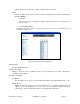
Specifications

Waters Network Systems 2800M/MR User’s Manual Page 81
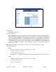
Figure 5.41
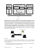
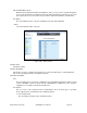
Figure 5.42 represents a typical configuration; a single supplicant, an authenticator and an
authentication server. B and C are in the internal network, D is the Authentication server running
RADIUS, switch at the central location which acts as Authenticator connecting to PC A. A is a
PC outside the controlled port, running Supplicant PAE. In this case, PC A wants to access the
services on device B and C. It first must exchange the authentication message with the
authenticator on the port it connected via EAPOL packet. The authenticator transfers the
supplicant’s credentials to Authentication server for verification. If successful, the authentication
server will notify the authenticator. PC A is then allowed to access B and C via the switch. If
there are two switches directly connected together instead of a single one, the link ports
connecting the two switches may have to perform two port roles: authenticator and supplicant,
because the traffic is bi-directional.
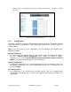
Figure 5.42
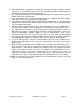
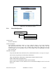
Figure 5.43 illustrates the procedure of 802.1X authentication. There are steps for the login
based on 802.1X port access control management. The protocol used in the right side is EAPOL
and the left side is EAP.
1. At the initial stage, supplicant A is unauthenticated so the port acting as an authenticator is
in unauthorized state. Access is blocked in this stage.
Supplicant A
B
C
Authentication server
Authenticator
LAN
Authenticator
PAE
Services Offered
by Authenticator
(e.g Bridge Relay)
Authenticator’s System
Authentication
Server’s System
Authentication
Server
Supplicant
PAE
Uncontrolled port Controlled port
MAC Enable
Port Authorize
Supplicant’s
System