INSTALLATION GUIDE AND OPERATING MANUAL ProSwitch Quad Series 3200 ProSwitch-QS3200 Modular Ethernet Switch Combine 10/100Mbps and 1000Mbps copper; 100 and 1000Mbps fiber ports CORPORATE HEADQUATERS 13705 26th Avenue, N., Suite 102 Minneapolis, MN 55441 Phone: 800.441.5319 Fax: 763.509.7450 E-mail: netinfo@wtrs.com www.watersnet.com MANUFACTURING/CUSTOMER SERVICE 2411 Seventh Street, NW Rochester, MN 55901 Phone: 800.328.2275 Fax: 507.252.3734 E-mail: netinfo@wtrs.
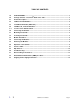
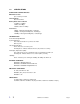
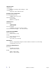
TABLE OF CONTENTS 1.0 SPECIFICATIONS..........................................................................................................................3 2.0 Package Contents - ProSwitch Quad Series 3200 ...................................................................5 2.1 Product Description .....................................................................................................................5 2.2 100Base-FX Fiber Modules.....................................................
1.
FIBER DISTANCE: 100Mbps Fiber Multimode: Full Duplex 2km, Half Duplex 1000Mbps Fiber Singlemode: 10km; multimode: 500m 412m NETWORK CABLE CONNECTORS: RJ-45 Shielded Female Ports 100Mbps: CAT5 UTP or better Fiber Port Connectors ST, SC or MTRJ Multimode or singlemode POWER SUPPLY: Input Voltage 110VAC @ 60Hz 240VAC @ 50Hz Power Consumption 33-42 Watts, depending on modules installed Internal Universal Power Supply: DC 3.
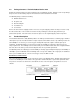
Package Contents - ProSwitch Quad Series 3200 2.0 Examine the shipping container for obvious damage prior to installing this product. Notify the carrier of any damage that you believe occurred during shipment. Ensure that the items listed below are included. The QS3200 package contains the following: QS3200 switch chassis AC power cord Rack mounting kit Four rubber feet User manual Remove the items from the shipping container.
2.
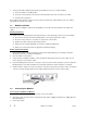
Your switch comes with two rack mounting brackets which can be used to mount the switch on an EIA 19” standard rack. Attach the brackets to the switch using the screws provided. Next, install the switch in the rack using the screws provided to attach the brackets to the rack. 3.0 Connecting the QS3200 The QS3200 switch has been designed to support all standard Ethernet media types within a single switch unit. The various media types supported along with the corresponding IEEE 802.3 and 802.
3. Set the power switch to ON and verify that the Power LED is lit. If it is not, check the following: The power switch is in the ON position. The power cord is properly connected to the wall outlet and to the power connection on the switch. The wall outlet is functional. Note: Network cable segments can be connected or disconnected from the switch while the power is on, without interrupting the operation of the switch. 3.
Connecting the 100Base-FX Modules 1. Remove the protective plastic covers from the fiber connectors on the module. 2. Plug the ST (or SC) connector on the fiber cable into the fiber socket on the module. 3. Connect the other end of the fiber optic segment to an appropriate device fitted with a 100Mbps adapter. 4. Check the LED indicators on the front of the switch to ensure that the module is operating correctly. 5. Power up the switch. Connecting the 1000Base-SX/LX Modules 1.
Red Full Duplex/Col indicators are illuminated when that port is in full duplex mode. The indicator is off when that port is in half duplex mode. Full Duplex/Col When a collision occurs on the network connected to a port, that Full Duplex/Col indicator blinks. 100Mbps 4.2 Green 100Mbps indicators are illuminated when the port is operating in 100Mbps mode. The indicator is off when the port is operating in 10Mbps mode.
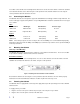
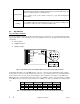
100Base-FX Fiber Modules (2 and 4-port modules) The fiber connectors (ST, SC or MTRJ) provide the link to multimode fiber cabling in either the two or four port modules. You can use the dip switch settings described in Table 2 to set the operating mode to half or full duplex.
1000Base Modules On the 1000Base modules, if the dip switch is set to OFF, N-Way is enabled. Full and half duplex cannot be enabled if auto-negotiation is in use. If auto-negotiation is disabled, the DIP switch for half and full duplex is enabled.
go to next step. If the problem is corrected, the Waters’ QS3200 switch and its associated cables are functioning properly. 6. If the problem continues, contact Waters Network Systems Customer Service at 800.328.2275 or email netinfo@wtrs.com for assistance. When Calling for Assistance Please be prepared to provide the following information. 1. A complete description of the problem, including the following points: a. b. c. d.
5.3 Shipping and Packaging Information Should you need to ship the unit back to Waters Network Systems, please follow these instructions: Package the unit carefully. It is recommended that you use the original container if available. Units should be wrapped in a "bubble-wrap" plastic sheet or bag for shipping protection. (You may retain all connectors and this Installation Guide.) CAUTION: Do not pack the unit in Styrofoam "popcorn" type packing material.