
Installation guide

WATERS NETWORK SYSTEMS ProSwitch-Xtreme Operating Manual Page 6
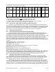
LED Indicators
PWR: Steady ON when power applied
SPEED (when LINK is ON): ON = 100Mbps; OFF = 10Mbps
LINK/ACT: Steady ON for LINK with no traffic, blinking indicates port is transmitting/receiving.
F/H (RJ45 ports only): ON = full-duplex, OFF = half-duplex
MTBF (Bellcore method)
Over 15 years MTBF
Email: carolynl@watersnet.com
Agency Approvals
UL Listed (UL 1950), cUL, CE
Emissions: meets FCC Part 15, Class B
Warranty: Limited lifetime
Made in USA
5.0 INSTALLATION
5.1 Inspecting the Package and Product
Examine the shipping container for obvious damage prior to installing this product; notify the carrier of any
damage that you believe occurred during shipment or delivery. Inspect the contents of this package for any signs of
damage and ensure that the items listed below are included.
This package should contain:
1 ProSwitch-Xtreme-Series Ethernet Switch with two Fiber Ports.
1 Installation and User Guide
1 Power Source Extended Temp. unit
Remove the ProSwitch-Xtreme-Series switch from the shipping container. Be sure to keep the shipping
container should you need to ship the unit at a later date.
In the event there are items missing or damaged, contact your supplier. If you need to return the unit, use the
original shipping container. Refer to Section 7, Troubleshooting, for specific return procedures.
5.2 Location of Xtreme 10/100Mbps Switch
5.2.1 Tabletop or Shelf Mounting
The ProSwitch-Xtreme Ethernet switch can be easily mounted on a tabletop, shelf or any suitable horizontal
surface, but has to be securely mounted through appropriate screws.
5.2.2 Wall (or vertical surface) Mounting
The ProSwitch-Xtreme switch is quite heavy because of its 18-gauge high-strength steel case enclosure.
Because of its weight, it is very important to select a sturdy place and carefully attach it to strong surface. Attaching it
to a metal surface is preferred to aid the thermal heat transfer from the case.
Each ProSwitch-Xtreme switch is normally mounted with screws in a vertical (cable connectors at the bottom)
position. The base plate of the unit has screw holes cut out, two top and two bottom. The spacing for the mounting
screws is a rectangle 3.35” x 8.25” (8.25cm x 21cm) center-to-center. Four user-supplied screws attach the
ProSwitch-Xtreme base plate to the vertical mounting surface.
5.3 Connecting Ethernet Media, and Special Strain-Relief Feature
Note – see also “Cable Strain Relief Feature, Section 5.5.
The ProSwitch-Xtreme switches can be connected to the following three media types: 100BASE-TX, 10BASE-
T and 100BASE-FX. CAT5 cables should be used when making 100BASE-TX connections. When the ports are used
as 10BASE-T ports, CAT3 may be used. In either case, the maximum distance for unshielded twisted pair cabling is
100 meters (328 ft). For fiber port 100BASE-FX multimode, 50/125 or 62.5/125 microns cabling can be used, whereas
for singlemode, 9/125 microns cabling should be used. Fiber cabling supports much longer cable distance and higher
bandwidths as compared to copper wiring.
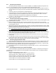
Media
IEEE Standard Connector
Twisted Pair (CAT3 or 5) 10BASE-T RJ45
Twisted Pair (CAT5) 100BASE-TX RJ45
Fiber (Multimode) 100BASE-FX SC
Fiber (Singlemode) 100BASE-FX SC
NOTE: It is recommended that high quality CAT5E cables (which work for both 10Mbps and 100Mbps) be used
whenever possible in order to provide flexibility in a mixed-speed network.