
Manual


PRODUCT SUPPORT 800.927.2120 8am - 6pm EST
RW ATLAS
Handshower on Bar
INSTALLATION GUIDELINES
Page 1 of 2
1.15.2013
These guidelines have been prepared for the professional contractor to aid in the installation of:
RW ATLAS HANDSHOWER ON BAR (STYLE# RWHS10)
All dimensions are based on original
specification and are subject to change and variation.
Please consult your Design Associate for current specifications.
SEE SERVICE PART DOCUMENT FOR PART ORDERING, AVAILABLE ON WATERWORKS.COM
Style No. RWHS10
SPECIFICATIONS:
Connection Type:
3
/
4
" Copper Compression
Recommended Pressure: 45 psi
Restricted Maximum Flow Rate: 2.5 gpm. For use with
automatic compensating valves rated at 2.5gpm.
IMPORTANT:
¾ To ensure this product is installed properly, you
must read and follow these guidelines.
¾ The owner/user of this product must keep this
information for future reference.
¾ Be sure your installation conforms to federal state,
and local codes. In the State of Massachusetts, all
installations must comply with the rules and
regulations set forth within 248 CMR.
¾ A diverter or wall valve (sold separately) control
on/off/volume and must be installed for each fitting
that will have water flowing to it.
¾ This product must be installed by a professional
licensed contractor and must be onsite prior to
rough-in, this allows the installer to visualize the
installation.
¾ Proper blocking in the wall is required.
¾ Inspect this product to ensure you have all the parts
required for proper installation.
¾ Use only a strap wrench or protected/smooth-jaw
wrench on any finished surface.
¾ DO NOT use putty on fittings.
ROUGH IN:
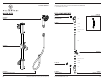
¾ See Figure - 01 for Steps 1-4.
1. Run a well supported 3/4" copper supply line from
the wall valve/diverter (sold separately) for
maximum flow.
2. Determine the ideal location of the handshower on
bar, based on user preferences. Install blocking to
properly secure unit. The distance from inlet to wall
support is 19-5/16".
3. Verify the supply is secure and level. Cap off the
supply and check for leaks.
4. Cut the copper line so it extend 15/16" from the
finished wall.
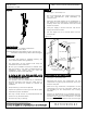
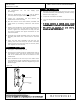
Figure - 01
19-
5
16
" FROM INLET
TO WALL MOUNT
15
16
" FROM
FINISHED WALL
ANCHOR
WALL MOUNT PLATE
SCREW
SET SCREW
HANDSHOWER
SLIDER
INLET
POST
O-RING
ESCUTCHEON
COMPRESSION NUT
COMPRESSION RING
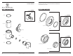
HANDSHOWER ON BAR INSTALLATION:
¾ See Figure - 01 for Steps 5-13.
5. Unthread and remove the compression nut and
compression ring, along with escutcheon and o-ring
from the inlet post.
6. Slide the o-ring, escutcheon, compression nut and
compression ring over the inlet pipe, making sure
the threading on the compression nut is facing
outwards.
7. Position the handshower on bar assembly onto the
supply pipe until it is fully seated into the inlet post
and then hand tighten
the compression nut. Slide
the escutcheon back towards the wall; and if the gap