EZ-ZONE PM ® User’s Manual PID Controller Models TOTAL CUSTOMER SATISFACTION 3 Year Warranty ISO 9001 Registered Company Winona, Minnesota USA 1241 Bundy Boulevard., Winona, Minnesota USA 55987 Phone: +1 (507) 454-5300, Fax: +1 (507) 452-4507 http://www.watlow.com 0600-0058-0000 Rev. J March 2010 Made in the U.S.A.
Safety Information Unit is a Listed device per Underwriters Laboratories®. It has been evaluated to United States and Canadian requirements for Hazardous Locations Class 1 Division II Groups A, B, C and D. ANSI/ISA 12.12.01-2007. File E184390 QUZW, QUZW7. See: www.ul.com We use note, caution and warning symbols throughout this book to draw your attention to important operational and safety information. A “NOTE” marks a short message to alert you to an important detail.
• All configuration information • User’s Manual • Factory Page Return Material Authorization (RMA) 1. Call Watlow Customer Service, (507) 454-5300, for a Return Material Authorization (RMA) number before returning any item for repair. If you do not know why the product failed, contact an Application Engineer or Product Manager. All RMA’s require: • Ship-to address • Bill-to address • Contact name • Phone number • Method of return shipment • Your P.O.
TC Table of Contents Chapter 1: Overview . . . . . . . . . . . . . . . . . . . . . . . . . . . . . . . . . . . . . 3 Standard Features and Benefits . . . . . . . . . . . . . . . . . . . . . . . . . . . . . . . . 3 A Conceptual View of the PM. . . . . . . . . . . . . . . . . . . . . . . . . . . . . . . . . . 4 Getting Started Quickly. . . . . . . . . . . . . . . . . . . . . . . . . . .
TC Table of Contents (cont.) Chapter 7: Profiling Page. . . . . . . . . . . . . . . . . . . . . . . . . . . . . . . . . 64 Profiling Menu . . . . . . . . . . . . . . . . . . . . . . . . . . . . . . . . . . . . . . . . . . . . 65 Chapter 8: Factory Page. . . . . . . . . . . . . . . . . . . . . . . . . . . . . . . . . . 68 Custom Menu. . . . . . . . . . . . . . . . . . . . . . . . .
1 Chapter 1: Overview The EZ-ZONE ® PM takes the pain out of solving your thermal loop requirements. Watlow’s EZ-ZONE PM controllers offer options to reduce system complexity and the cost of controlloop ownership. You can order the EZ-ZONE PM as a PID controller or an over-under limit controller, or you can combine both functions in the PM Integrated Limit Controller.
A Conceptual View of the PM The flexibility of the PM’s software and hardware allows a large range of configurations. Acquiring a better understanding of the controller’s overall functionality and capabilities while at the same time planning out how the controller can be used will deliver maximum effectiveness in your application. It is useful to think of the controller in three parts: inputs; procedures; and outputs.
Getting Started Quickly the default value of 75 °F to the desired value. As the Set Point increases above the Process Value, output 1 will come on and it will now begin driving your output device. The PV function as shown in the graphic below is only available with PM4/8/9 models. The PM control has a page and menu structure that is listed below along with a brief description of its purpose. Setup Page Push and hold the up and down keys (¿ ¯) for 6 seconds to enter.
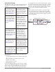
EZ-ZONE® PM PID Model System Diagram Universal Sensor Input, Configuration Communications, Red/Green 7-Segment Display Output Functions Input Functions Input sensor None Profile start/stop Profile start Profile hold/resume Profile disable TRU-TUNE+® disable Control outputs off Manual/auto mode Tune Idle set point Force alarm Loop & alarms off Silence alarm Alarm reset Lock keypad Restore user settings Network remote user interface, personal computer, programmable logic controller, humanmachine interfa
2 Dimensions Chapter 2: Install and Wire 1/32 DIN 15.9 mm 0.63 in 53.3 mm 2.10 in 101.6 mm 4.00 in 31.2 mm 1.23 in 30.9 mm 1.22 in Side Front Top 45.2 mm (1.78 in) 22.4 mm (0.88 in) Recommended panel spacing panel thickness 1.53 to 9.52 mm (0.060 to 0.375) 21.6 mm (0.85 in) 21.6 mm (0.
1/16 DIN 15.8 mm (0.62 in) 101.6 mm (4.00 in) 53.3 mm (2.10 in) 53.3 mm (2.10 in) Side Front 51.2 mm (2.02 in) Top L1 L3 K1 K3 99 J1 J3 CF 98 L2 L4 CD K2 K4 CE T1 T2 B5 S1 S2 D6 R1 R2 D5 Back 45.2 mm (1.78 in) 45.2 mm (1.78 in) panel thickness 1.53 to 9.52 mm (0.060 to 0.375) 21.6 mm (0.85 in) 21.6 mm (0.
1/8 DIN (PM8) Vertical 15.75 mm (0.62 in) 1.52 mm (0.06 in) 53.34 mm (2.10 in) 100.33 mm (3.95 in) 10.16 mm (0.40 in) 30.73 mm (1.21 in) 54.86 mm (2.16 in) 101.60 mm (4.00 in) 1/8 DIN (PM8) Vertical Recommended Panel Spacing 45.2 mm (1.78 in) 92.3 mm (3.635 in) Panel thickness (0.060 in) 1.53 mm to (0.375 in) 9.52 mm 21.6 mm (0.85 in) 21.6 mm (0.
1/8 DIN (PM9) Horizontal 15.75 mm (0.62 in) 1.52 mm (0.06 in) 100.33 mm (3.95 in) 54.86 mm (2.16 in) 53.34 mm (2.10 in) 10.16 mm (0.40 in) 30.73 mm (1.21 in) 101.60 mm (4.00 in) 1/8 DIN (PM9) Horizontal Recommended Panel Spacing 92.3 mm (3.635 in) 45.2 mm (1.78 in) Panel thickness (0.060 in) 1.53 mm to (0.375 in) 9.52 mm 21.6 mm (0.85 in) 21.6 mm (0.
1/4 DIN (PM4) 15.75 .62 100.33 3.95 1.52 .06 100.33 3.95 12.70 .50 30.73 1.21 100.84 3.97 1/4 DIN (PM4) Recommended Panel Spacing 92.3 3.635 92.3 3.635 21.6 .85 Panel thickness .060 (1.53) to .375 (9.52) 21.6 .
Installation Don't be afraid to apply enough pressure to properly install the controller. The seal system is compressed more by mating the mounting collar tighter to the front panel (see pictures above). If you can move the case assembly back and forth in the cutout, you do not have a proper seal. The tabs on each side of the mounting collar have teeth that latch into the ridges on the sides of the controller.
Returning the Controller to its Case 1. Ensure that the orientation of the controller is correct and slide it back into the housing. Note: The controller is keyed so if it feels that it will not slide back in do not force it. Check the orientation again and reinsert after correcting. 2. Using your thumbs push on either side of the controller until both latches click. Chemical Compatibility This product is compatible with acids, weak alkalis, alcohols, gamma radiation and ultraviolet radiation.
Wiring Terminal Definitions for Slots A Slot A Output Terminal Function Configuration common (Any switched dc output can use this common.
Back View Slot Orientation 1/8 DIN Vertical PM8 Power A C E D B Dig I/O 5 & 6 485 Comms Dig I/O 5 & 6 485 Comms C Input 1 Input 1 E Output 2 Output 2 A Output 1 Output 1 Power Back View Slot Orientation 1/8 DIN Horizontal PM9 Input 1 A D E C Dig I/O 5 & 6 485 Comms Communications Card Output 2 Digital I/O 7 - 12 Output 1 D B Power Back View Slot Orientation 1/4 DIN Horizontal PM4 Output 3 Output 4 Input 2 B EZ-ZONE PM Isolation Blocks Mechanical Relay, Solid-State Relay,
Óç Warning: Use National Electric (NEC) or other country-specific standard wiring and safety practices when wiring and connecting this controller to a power source and to electrical sensors or peripheral devices. Failure to do so may result in damage to equipment and property, and/or injury or loss of life. Note: Maximum wire size termination and torque rating: • 0.0507 to 3.30 mm2 (30 to 12 AWG) single-wire termination or two 1.31 mm2 (16 AWG) • 0.8 Nm (7.0 lb.-in.
Óç Warning: Use National Electric (NEC) or other country-specific standard wiring and safety practices when wiring and connecting this controller to a power source and to electrical sensors or peripheral devices. Failure to do so may result in damage to equipment and property, and/or injury or loss of life. Input 1 Thermocouple Slot A • • • • - S1 + R1 Input 1 RTD Note: Maximum wire size termination and torque rating: • 0.0507 to 3.30 mm2 (30 to 12 AWG) single-wire termination or two 1.
Óç Input 1 Thermistor Warning: Use National Electric (NEC) or other country-specific standard wiring and safety practices when wiring and connecting this controller to a power source and to electrical sensors or peripheral devices. Failure to do so may result in damage to equipment and property, and/or injury or loss of life.
Óç Digital Output 5, 6 Slot C 98 Warning: Use National Electric (NEC) or other country-specific standard wiring and safety practices when wiring and connecting this controller to a power source and to electrical sensors or peripheral devices. Failure to do so may result in damage to equipment and property, and/or injury or loss of life. Note: Maximum wire size termination and torque rating: • 0.0507 to 3.30 mm2 (30 to 12 AWG) single-wire termination or two 1.31 mm2 (16 AWG) • 0.8 Nm (7.0 lb.-in.
Óç Warning: Use National Electric (NEC) or other country-specific standard wiring and safety practices when wiring and connecting this controller to a power source and to electrical sensors or peripheral devices. Failure to do so may result in damage to equipment and property, and/or injury or loss of life.
Óç Warning: Use National Electric (NEC) or other country-specific standard wiring and safety practices when wiring and connecting this controller to a power source and to electrical sensors or peripheral devices. Failure to do so may result in damage to equipment and property, and/or injury or loss of life. Output 1 Solid-State Relay, Form A Slot A normally open L1 common K1 • 0.
Óç Warning: Use National Electric (NEC) or other country-specific standard wiring and safety practices when wiring and connecting this controller to a power source and to electrical sensors or peripheral devices. Failure to do so may result in damage to equipment and property, and/or injury or loss of life. Note: Maximum wire size termination and torque rating: • 0.0507 to 3.30 mm2 (30 to 12 AWG) single-wire termination or two 1.31 mm2 (16 AWG) • 0.8 Nm (7.0 lb.-in.
Óç Warning: Use National Electric (NEC) or other country-specific standard wiring and safety practices when wiring and connecting this controller to a power source and to electrical sensors or peripheral devices. Failure to do so may result in damage to equipment and property, and/or injury or loss of life.
Warning: Use National Electric (NEC) or other country-specific standard wiring and safety practices when wiring and connecting this controller to a power source and to electrical sensors or peripheral devices. Failure to do so may result in damage to equipment and property, and/or injury or loss of life.
Óç Connecting a Computer to PM Controls Using B&B 485 to USB Converter Warning: Use National Electric (NEC) or other country-specific standard wiring and safety practices when wiring and connecting this controller to a power source and to electrical sensors or peripheral devices. Failure to do so may result in damage to equipment and property, and/or injury or loss of life. Note: Maximum wire size termination and torque rating: • 0.0507 to 3.30 mm2 (30 to 12 AWG) single-wire termination or two 1.
3 Chapter 3: Keys and Displays Upper (Left, 32nd DIN) Display: 1/32 DIN (PM3) In the Home Page, displays the process value, otherwise displays the value of the parameter in the lower display. Zone Display: Indicates the controller zone.
Responding to a Displayed Message An active message will cause the display to toggle between the normal settings and the active message in the upper display and [Attn] in the lower display. Your response will depend on the message and the controller settings. Some messages, such as Ramping and Tuning, indicate that a process is underway.
4 Chapter 4: Home Page Default Home Page Parameters Watlow’s patented user-defined menu system improves operational efficiency. The user-defined Home Page provides you with a shortcut to monitor or change the parameter values that you use most often. The default Home Page is shown on the following page. When a parameter normally located in the Setup Page or Operations Page is placed in the Home Page, it is accessible through both.
Home Page Defaults Home Page Display Parameter Page and Menu All Models 1 Active Process Value (1) Numerical value Operations Page, Monitor Menu 2 Active Set Point (1) Numerical value Operations Page, Monitor Menu 3 User Control Mode (1) [C;M1] Operations Page, Monitor Menu 4 Heat Power (1) [h;pr1] Operations Page, Monitor Menu 5 Cool Power (1) [C;pr1] Operations Page, Monitor Menu 6 Autotune (1) [aut1] Operations Page, Loop Menu 7 Idle (1) [id;s1] Operations Page, Loop Menu 8
Navigating the EZ-ZONE® PM PID Controller Applies to All Models - 1/16 DIN Shown Below ® ® ® ® [``Ai] [``70] [``70] [Cust] [`Set] [``72] [``72] [fCty] Home Page from anywhere: Press the Infinity Factory Page from Home Page: Press both the Advance ‰ and Infinity ˆ keys for six seconds. Key ˆ for two seconds to return to the Home Page. ® ® [``70] [``Ai] [``72] [oper] Operations Page from Home Page: Press both the Up ¿ and Down ¯ keys for three seconds.
Display Conventions Used in the Menu Pages To better understand the menu pages that follow review the naming conventions used. When encountered throughout this document, the word "default" implies as shipped from the factory. Each page (Operations, Setup, Profile and Factory) and their associated menus have identical headers defined below: Header Name Visual information from the control is displayed to the observer using a fairly standard 7 segment display.
bus the reference to Map 1 and Map 2 registers for each of the various parameters. If the new functions, namely; Linearization, Process Value and Real Time Clock are to be used than use Map 2 Modbus regis ters. The Data Map [map] for Modbus registers can be changed in the Setup Page under the [Com] Menu. This setting will apply across the control. It should also be noted that some of the cells in the Modbus column contain wording pertaining to an offset.
5 Chapter 5: Operations Page Navigating the Operations Page To go to the Operations Page from the Home Page, press both the Up ¿ and Down ¯ keys for three seconds. [``Ai] will appear in the upper display and [oPEr] will appear in the lower display. • Press the Up ¿ or Down ¯ key to view available menus. On the following pages top level menus are identified with a yellow background color. • Press the Advance Key ‰ to enter the menu of choice.
Operations Page Display Parameter Name Description Range Default Modbus Relative Address CIP Class Instance Attribute hex (dec) Profibus Index Paqrameter ID Data Type & Read/ Write [``Ai] [oPEr] Analog Input Menu Instance 1 Map 1 Map 2 360 360 Instance 2 Map 1 Map 2 440 450 0x68 (104) 1 1 0 4001 float R None [nonE] None (61) [OPEn] Open (65) [FAiL] Fail (32) [Shrt] Shorted (127) [`E;M] Measurement Error (140) [E;CAL] Bad Calibration Data (139) [Er;Ab] Ambient Error (9) [E;;Rtd] RTD Error (141
Operations Page Display No Display Parameter Name Description Linearization (1) Output Error View reported cause for Linearization output malfunction.
Operations Page Display Parameter Name Description Range Default Modbus Relative Address CIP Class Instance Attribute hex (dec) Profibus Index Paqrameter ID Data Type & Read/ Write [`dio] [oPEr] Digital Input/Output Menu ---- Instance 1 Map 1 Map 2 1012 1132 Offset to next instance equals +30 0x6A (106) 1 to 2 7 90 6007 uint R Digital Input (5 to 6) [`iact] Inactive (41) Event Status [``act] Active (5) View this event input state.
Operations Page Display Parameter Name Description Range Default Modbus Relative Address CIP Class Instance Attribute hex (dec) Profibus Index Paqrameter ID Data Type & Read/ Write [Loop] [oPEr] Control Loop Menu [`r;En] [ r.En] Control Loop (1) Remote Enable Enable this loop to switch control to the remote set point. [``no] No [`YES] Yes No Instance 1 Map 1 Map 2 2200 2680 0x6B (107) 1 0x15 (21) 48 7021 uint RWES [`r;ty] [ r.
Operations Page Default Modbus Relative Address CIP Class Instance Attribute hex (dec) 0.001 to 9,999.000°F or units -1,110.555 to 5,555.000°C 25.0°F or units 14.0°C Instance 1 Map 1 Map 2 1892 2370 Control Loop (1) Cool Hysteresis Set the control switching hysteresis for on-off control. This determines how far into the “on” region the process value needs to move before the output turns on. 0.001 to 9,999.000°F or units -1,110.555 to 5,555.000°C 3.0°F or units 2.
Operations Page Parameter Name Description Display Range Default Modbus Relative Address CIP Class Instance Attribute hex (dec) 32.0°F or units 0.0°C Instance 1 Map 1 Map 2 1482 1882 Data Type & Read/ Write Profibus Index Paqrameter ID 0x6D (109) 1 to 4 2 18 9002 float RWES 0x6D (109) 1 to 4 1 19 9001 float RWES 0x6D (109) 1 to 4 9 ---- 9009 uint R 0x6D (109) 1 to 4 0xC (12) ---- 9012 uint R [ALM] [oPEr] Alarm Menu [`A;Lo] [ A.Lo] [`A;hi] [ A.
Operations Page Display No Displayed Parameter Name Description Alarm (1 to 4) Alarm Clear Request Write to this register to clear an alarm Range Default Clear (1003) 0 Modbus Relative Address CIP Class Instance Attribute hex (dec) Instance 1 Map 1 Map 2 1504 1904 Data Type & Read/ Write Profibus Index Paqrameter ID 0x6D (109) 1 to 4 0xD (13) ---- 9013 uint W 0x6D (109) 1 to 4 0xE (14) ---- 9014 uint W 0x6D (109) 1 to 4 0x0B (11) ---- 9011 uint R 0x6D (109) 1 to 4 0x0A (10) ----
Operations Page Display Parameter Name Description Range Default Modbus Relative Address CIP Class Instance Attribute hex (dec) Profibus Index Paqrameter ID Data Type & Read/ Write [P;ACr] [PACr] Profile Status Action Request [nonE] None (61) [step] Step Start (89) [`End] Terminate (148) [rESU] Resume (147) [PAUS] Pause (146) [ProF] Profile (77) None Instance 1 Map 1 Map 2 2540 4360 0x7A (122) 1 0xB (11) 205 22011 uint RW [`StP] [ StP] Profile Status Active Step View the currently runnin
Operations Page Display Parameter Name Description Range Default Modbus Relative Address CIP Class Instance Attribute hex (dec) Profibus Index Paqrameter ID Data Type & Read/ Write [Ent2] [Ent2] Profile Status Active Event Output 2 View or change the event output states. [`off] Off (62) [``on] On (63) Off Instance 1 Map 1 Map 2 2548 4514 0x7A (122) 1 0xF (15) ---- 22015 uint RW [``JC] [ JC] Profile Status Jump Count Remaining View the jump counts remaining for the current loop.
6 Chapter 6: Setup Page Navigating the Setup Page To go to the Setup Page from the Home Page, press both the Up ¿ and Down ¯ keys for six seconds. [``Ai] will appear in the upper display and [`Set] will appear in the lower display. • Press the Up ¿ or Down ¯ key to view available menus. On the following pages top level menus are identified with a yellow background color. •Press the Advance Key ‰ to enter the menu of choice.
[`leu] Level [``Fn] Digital Input Function [``fi] Instance [gLbL] [`Set] Global Menu [`C_F] Display Units [AC;LF] AC Line Frequency [r;typ] Ramping Type [p;typ] Profile type [`gse] Guaranteed Soak Enable [gsd1] Guaranteed Soak Deviation 1 [`si;a] Source instance A [`si;b] Source instance B [poti] Power Out Time [C;led] Communications LED Action [2one] Zone Action [Chan] Channel Action [d;prs] Display Pairs [`d;ti] Menu Display Timer [Usr;s] User Save [Us
Setup Page Display Parameter Name Description Range Default CIP Modbus RelaClass tive Instance Address Attribute hex (dec) Profibus Index Parameter ID Data Type & Read/ Write [``Ai] [`Set] Analog Input Menu [`Sen] [ SEn] Analog Input (1) Sensor Type Set the analog sensor type to match the device wired to this input. Note: There is no open-sensor detection for process inputs.
Setup Page Display Parameter Name Description Range Default CIP Modbus RelaClass tive Instance Address Attribute hex (dec) Profibus Index Parameter ID Data Type & Read/ Write [`r;hi] [ r.hi] Analog Input (1) -1,999.000 to 9,999.000 Range High Set the high range for this function block's output. 9,999 Instance 1 0x68 (104) 1 Map 1 Map 2 0x12 (18) 394 394 9 4018 float RWES [`P;EE] [ P.EE] Analog Input (1) Process Error Enable Turn the Process Error Low feature on or off.
Setup Page Display Parameter Name Description Range Default CIP Modbus RelaClass tive Instance Address Attribute hex (dec) Profibus Index Parameter ID Data Type & Read/ Write [Unit] [Unit] Linearization (1) Units Set the units of Source A which is Analog Input 1.
Setup Page CIP Modbus RelaClass tive Instance Address Attribute hex (dec) Data Type & Read/ Write Profibus Index Parameter ID Instance 1 0x86 (134) 1 Map 1 Map 2 ---3584 0xD (13) 167 34013 float RWES 5.0 Instance 1 0x86 (134) 1 Map 1 Map 2 ---3604 0x17 (23) 168 34023 float RWES -1,999.000 to 9,999.000 6.0 Instance 1 0x86 (134) 1 Map 1 Map 2 ---3586 0xE (14) 169 34014 float RWES Linearization (1) Output Point 7 Set the value that will be mapped to input 7. -1,999.000 to 9,999.000 6.
Setup Page Data Type & Read/ Write Parameter ID Instance 1 0x7E (126) 1 Map 1 Map 2 ---3334 0x1C (28) ---- 26028 uint RWES HFt Instance 1 0x7E (126) 1 Map 1 Map 2 ---3336 0x1D (29) ---- 26029 uint RWES 0.0 Instance 1 0x7E (126) 1 Map 1 Map 2 ---3330 0x1A (26) ---- 26026 float RWES Instance 1 0x6A (106) 5 to 6 Map 1 Map 2 1 1000 1120 82 6001 uint RWES 83 6005 uint RWES Parameter Name Description [p;unt] [P.
Setup Page Display [``Fi] [ Fi] Parameter Name Description Digital Output (5 to 6) Function Instance Set the instance of the function selected above.
Setup Page Display [`leu] [ LEv] [``Fn] [ Fn] Parameter Name Description Digital Input (5 to 6) Level Select which action will be interpreted as a true state.
Setup Page Display [``Fi] [ Fi] Parameter Name Description Range Default Digital Input (5 to 7) 0 to 4 Function Instance Select which Digital Input will be triggered by a true state. CIP Modbus RelaClass tive Instance Address Attribute hex (dec) Instance 1 0x6E (110) 5 to 7 Map 1 Map 2 4 1326 1566 0 Data Type & Read/ Write Profibus Index Parameter ID 139 10004 uint RWES Offset to next instance (Map 1 & Map 2) equals +20 [LooP] [`Set] Control Loop Menu [`h;Ag] [ h.
Setup Page Display Parameter Name Description Range Default 0.0 CIP Modbus RelaClass tive Instance Address Attribute hex (dec) Data Type & Read/ Write Profibus Index Parameter ID Instance 1 0x97 (151) 1 Map 1 Map 2 ---- - - - 0x1C (28) ---- 8051 float RWES [p;dl] [ P.dL] Control Loop (1) 0.0 to 5.0 Peltier Delay Set a value that will cause a delay when switching from heat mode to cool mode.
Setup Page Display Parameter Name Description Range Default CIP Modbus RelaClass tive Instance Address Attribute hex (dec) Profibus Index Parameter ID Data Type & Read/ Write [`L;dd] [ L.dd] Control Loop (1) -1,999.000 to 9,999.000°F Open Loop Detect Deor units viation -1,110.555 to 5,555.000°C Set the value that the process must deviate from the set point to trigger an open-loop error. 10.0°F or units 6.
Setup Page Display Parameter Name Description Range CIP Modbus RelaClass tive Instance Address Attribute hex (dec) Default Data Type & Read/ Write Profibus Index Parameter ID 83 6005 uint RWES 84 6006 uint RWES 85 6002 uint RWES 86 6003 float RWES 87 6009 float RWES [otpt] [`Set] Output Menu [``Fn] [ Fn] [``Fi] [ Fi] Output Digital (1 to 2) Function Select what function will drive this output.
Setup Page Display [`o;hi] [ o.hi] Parameter Name Description Output Digital (1 to 2) High Power Scale The power output will never be greater than the value specified and will represent the value at which output scaling stops. Range Default 0.0 to 100.0% 100.
Setup Page Display Parameter Name Description Range CIP Modbus RelaClass tive Instance Address Attribute hex (dec) Data Type & Read/ Write Profibus Index Parameter ID 9,999.0°F Instance 1 0x76 (118) or units Map 1 Map 2 1 0xC (12) 5,537.0°C 742 862 102 18012 float RWES Default [`r;hi] [ r.hi] Output Process (1) -1,999.000 to 9,999.000°F Range High or units Set the maximum value -1,128.000 to 5,537.000°C of the retransmit value range in process units.
Setup Page Display [`A;hy] [ A.hy] [`A;Lg] [ A.Lg] [`A;Sd] [ A.Sd] Parameter Name Description Range Alarm (1 to 4) Hysteresis Set the hysteresis for an alarm. This determines how far into the safe region the process value needs to move before the alarm can be cleared. 0.001 to 9,999.000°F or units 0.001 to 5,555.000°C Alarm (1 to 4) Logic Select what the output condition will be during the alarm state. [`AL;C] Close On Alarm (17) [`AL;o] Open On Alarm (66) Default 1.0°F or units 1.
Setup Page Display [`A;Si] [ A.Si] Parameter Name Description Alarm (1 to 4) Silencing Turn alarm silencing on to allow the user to disable this alarm.
Setup Page Display [``Fn] [ Fn] Function Key (1 to 2) Digital Input Function Program the EZ Key to trigger an action. Functions respond to a level state change or an edge level change.
Setup Page Display Parameter Name Description Range Default CIP Modbus RelaClass tive Instance Address Attribute hex (dec) Profibus Index Parameter ID Data Type & Read/ Write Time Instance 1 0x7A (122) 1 Map 1 Map 2 26 (38) ---4414 ---- 22038 uint RWE Profile [StPt] Set Point (85) Profile Type [`Pro] Process (75) Set the profile startup to be based on a set point or a process value.
Setup Page Display Parameter Name Description Range Default CIP Modbus RelaClass tive Instance Address Attribute hex (dec) Profibus Index Parameter ID Data Type & Read/ Write On Instance 1 0x6A (103) 1 Map 1 Map 2 ---2352 0x1B (27) ---- 3027 uint RWES 1 to 10 2 Instance 1 0x6A (103) 1 Map 1 Map 2 ---2354 0x1C (28) ---- 3028 uint RWES Global Menu Display Time Time delay in toggling between channel 1 and channel 2.
Setup Page Display Parameter Name Description Range Default CIP Modbus RelaClass tive Instance Address Attribute hex (dec) Profibus Index Parameter ID Data Type & Read/ Write [`PAr] [ PAr] Communications [none] None (61) Parity Modbus (1) [EuEn] Even (191) Set the parity of this con- [`odd] Odd (192) troller to match the parity of the serial network.
7 Chapter 7: Profiling Page Navigating the Profiling Page Note: Some of these menus and parameters may not appear, depending on the controller's options. See model number information in the Appendix for more information. If there is only one instance of a menu, no submenus will appear. How to Start a Profile The Profiling Page allows you to enter your ramp and soak profile information. After defining the profile follow the steps below to run the profile: 1.
Profiling Page Display Parameter Name Description Range Default Modbus Relative Address ---- ---- CIP Class ParamInstance eter ID Attribute hex (dec) Data Type & Read/ Write [``P1] [prof] Profiling Menu [``p1] Step Select a step to edit or view. [ P1] to [``p4] [ P4] [S;typ] [S.typ] [t;SP1] [t.
Profiling Page Display [rate] [rAtE] W;P1] [W.P1] Parameter Name Description Range Default Step Type Parameters Rate Select the rate for ramping in degrees or units per minute. 0 to 9,999.000°F or units per minute 0 to 5,555.000°C per minute Step Type Parameters Wait For Process Value Select which analog input Wait For Process will use. -1,999.000 to 9,999.000°F or units -1,128.000 to 5,537.000°C 0.
Profiling Page Display [~~JC] [ JC] [~End] [ End] Ent1] [Ent1] [Ent2] [Ent2] Parameter Name Description Range Default 0 to 9,999 Step Type Parameters Jump Count Set the number of jumps. A value of 0 creates an infinite loop. Loops can be nested four deep.
8 Chapter 8: Factory Page Navigating the Factory Page To go to the Factory Page from the Home Page, press and hold both the Advance ‰ and Infinity ˆ keys for six seconds. • Press the Advance Key ‰ to enter the menu of choice. • If a submenu exists (more than one instance), press the Up ¿ or Down ¯ key to select and then press the Advance Key ‰ to enter. • Press the Up ¿ or Down ¯ key to move through available menu prompts.
Factory Page Display Parameter Name Description Range Default Modbus Relative Address CIP Data Class Type Profibus ParamInstance & Index eter ID Attribute Read/ hex (dec) Write [Cust] [fcty] Custom Menu [`par] [ Par] Custom Parameter 1 to 20 Select the parameters that will appear in the Home Page. The Parameter 1 value will appear in the upper display of the Home Page. It cannot be changed with the Up and Down Keys in the Home Page.
Factory Page Display Parameter Name Description Range Default Modbus Relative Address CIP Data Class Type Profibus ParamInstance & Index eter ID Attribute Read/ hex (dec) Write [LoC;P] [LoC.P] Security Setting Profiling Page Change the security level of the Profiling Page. 1 to 3 3 ---- ---- ---- 3008 uint RWE [pas;e] [LoC.P] Security Setting Password Enable Turn security features on or off.
Factory Page Display Parameter Name Description Range Default Modbus Relative Address CIP Data Class Type Profibus ParamInstance & Index eter ID Attribute Read/ hex (dec) Write [ULoC] [FCty] Security Setting Menu [Code] [CodE] Security Setting Customer Specific Public Key If Rolling Password turned on, generates a random number when power is cycled. If Rolling Password is off fixed number will be displayed.
Factory Page Modbus Relative Address CIP Data Class Type Profibus ParamInstance & Index eter ID Attribute Read/ hex (dec) Write Display Parameter Name Description [ELi;o] [ELi.o] Calibration (1 to 2) Electrical Input Offset Change this value to calibrate the low end of the input range. -1,999.000 to 9,999.000 0.0 Instance 1 Map 1 Map 2 378 378 Instance 2 Map 1 Map 2 458 468 0x68 (104) 1 to 2 0xA (10) ---- 4010 float RWES [ELi;S] [ELi.
9 Chapter 9: Features Saving and Restoring User Settings. . . . . . . . . . . . . . . . . . . . . . . . . . 74 Programming the Home Page. . . . . . . . . . . . . . . . . . . . . . . . . . . . . . 74 Tuning the PID Parameters. . . . . . . . . . . . . . . . . . . . . . . . . . . . . . . . 74 Manual Tuning . . . . . . . . . . . . . . . . . . . . . . . . . . . . . . . . . . . . . . . . . .
Saving and Restoring User Settings Recording setup and operations parameter settings for future reference is very important. If you unintentionally change these, you will need to program the correct settings back into the controller to return the equipment to operational condition. After you program the controller and verify proper operation, use User Save Set [USr;S] (Setup Page, Global Menu) to save the settings into either of two files in a special section of memory.
Manual Tuning In some applications, the autotune process may not provide PID parameters for the process characteristics you desire. If that is the case, you may want to tune the controller manually. 1. Apply power to the controller and establish a set point typically used in your process. 2. Go to the Operations Page, Loop Menu, and set Heat Proportional Band [`h;Pb] and/or Cool Proportional Band [`C;Pb] to 5. Set Time Integral [``ti] to 0. Set Time Derivative [``td] to 0. 3.
When autotuning is complete, the PID parameters should provide good control. As long as the loop is in the adaptive control mode, TRU-TUNE+ ® continuously tunes to provide the best possible PID control for the process. ç WARNING! During autotuning, the controller sets the output to 100 percent and attempts to drive the process variable toward the set point. Enter a set point and heat and cool power limits that are within the safe operating limits of your system.
Filter Time Constant Scale High and Scale Low Filtering smoothes an input signal by applying a first-order filter time constant to the signal. Filtering the displayed value makes it easier to monitor. Filtering the signal may improve the performance of PID control in a noisy or very dynamic system. Adjust the filter time interval with Filter Time [`FiL] (Setup Page, Analog Input Menu). Example: With a filter value of 0.
NO-ARC Relay A NO-ARC relay provides a significant improvement in the life of the output relay over conventional relays. Conventional mechanical relays have an expected life of 100,000 cycles at the rated full-load current. The shorter life for conventional relays is due to the fact that when contacts open while current is flowing metal degradation occurs. This action produces unavoidable electrical arcing causing metal to transfer from one contact to the other.
is present, the controller will perform closed-loop control. Closed-loop control uses a process sensor to determine the difference between the process value and the set point. Then the controller applies power to a control output load to reduce that difference. If a valid input signal is not present, the controller will indicate an input error message in the upper display and [Attn] in the lower display and respond to the failure according to the setting of Input Error Failure [FAiL].
[MAn] for manual mode. Use the Up ¿ or Down ¯ keys to select [AUto]. The automatic set point value will be recalled from the last automatic operation. Changes take effect after three seconds or immediately upon pressing either the Advance Key ‰ or the Infinity Key ˆ. On-Off Control On-off control switches the output either full on or full off, depending on the input, set point and hysteresis values.
Proportional plus Integral plus Derivative (PID) Control Use derivative (rate) control to minimize the overshoot in a PI-controlled system. Derivative (rate) adjusts the output based on the rate of change in the temperature or process value. Too much derivative (rate) will make the system sluggish. Derivative action is active only when the process value is within twice the proportional value from the set point. Adjust the derivative with Time Derivative [``td] (Operations Page, Loop Menu).
fect of analog, phase-angle fired control. Select the AC Line Frequency [AC;LF] (Setup Page, Global Menu), 50 or 60 Hz.
View or change alarm set points with Low Set Point [`A;Lo] and High Set Point [`A;hi] (Operations Page, Alarm Menu).
100%. Once there, the control will then begin to monitor the Open Loop Detect Deviation [`l; d d ] as it relates to the value entered for the Open Loop Detect Time [`l; d t] . If the specified time period expires and the deviation does not occur, an Open Loop Error will be triggered. Once the Open Loop Error condition exists the control mode will go off. Note: All prompts identified in this section can be found in the Loop Menu of the Setup Page.
[LoC;P] to 2. If Set Lockout Security [SLoC] is set to 2 or higher and the Read Lockout Security [rLoC] is set to 2, the Profiling Page and Home Pages can be accessed, and all writable parameters can be written to. Pages with security levels greater than 2 will be locked out (unaccessible).
4. Execute the calculation defined below (7b or 8b) for either the User or Administrator. 5. Enter the result of the calculation in the upper display by using the Up ¿ or Down ¯ arrow keys or use EZ-ZONE Confgurator Software. 6. Exit the Factory Page by pushing and holding the Infinity ˆ key for two seconds. Formulas used by the User and the Administrator to calculate the Password follows: Passwords equal: 7. User a. If Rolling Password [roll] is Off, Password [ pass] equals User Password [ pas ; u ] .
Software Configuration Using EZ-ZONE® Configurator Software To enable a user to configure the PM control using a personal computer (PC), Watlow has provided free software for your use. If you have not yet obtained a copy of this software insert the CD (Controller Support Tools) into your CD drive and install the software.
In the previous screen shot the PM is shown highlighted to bring greater clarity to the control in focus. Any EZ-ZONE device on the network will appear in this window and would be available for the purpose of configurationor monitoring. After clicking on the control of choice simply click the next button once again. The next screen appears below. more clarity for the area of focus by not displaying unwanted menus ad parameters.
Lastly, when the configuration is complete click the "Finish" button at the bottom right of the previous screen shot. The screen that follows this action can be seen below. The user can save the file to any folder of choice. Although the PM control now contains the configuration (because the previous discussion focused on doing the configuration on-line) it is suggested that after the configuration process is completed that the user save this file on the PC for future use.
Chapter 10: Appendix Troubleshooting Alarms, Errors and Control Issues Indication Description Possible Causes Alarm won’t clear or reset Alarm will not clear or reset with keypad or digital input • Alarm latching is active Alarm won’t occur Alarm will not activate output • Alarm silencing is active • Alarm blocking is active • Alarm is set to incorrect output Corrective Action • Reset alarm when process is within range or disable latching • Alarm set to incorrect output • Set output to correct ala
[LP;o1] Loop Open Error Open Loop Detect is active and the process value did not deviate by a user-selected value in a user specified period. • Setting of Open Loop Detect Time incorrect • Setting of Open Loop Detect Deviation incorrect • Thermal loop is open • Set correct Open Loop Detect Time for application • Set correct Open Loop Deviation value for application • Determine cause of open thermal loop: misplaced sensors, load failure, loss of power to • Open Loop Detect function not load, etc.
Indication Description Possible Causes Corrective Action Process doesn’t control to set point Process is unstable or never reaches set point • Controller not tuned correctly Temperature runway Process value continues to increase or decrease past set point. • Controller output incorrectly programmed • Thermocouple reverse wired [`100] Device Error [rEtn] Controller displays internal mal- • Controller defective function message at power up.
Modbus - Programmable Memory Blocks Assembly Definition Addresses and Assembly Working Addresses Assembly Definition Addresses 40 & 41 42 & 43 44 & 45 46 & 47 48 & 49 50 & 51 52 & 53 54 & 55 56 & 57 58 & 59 60 & 61 62 & 63 64 & 65 66 & 67 68 & 69 70 & 71 72 & 73 74 & 75 76 & 77 78 & 79 Assembly Working Addresses 200 & 201 202 & 203 204 & 205 206 & 207 208 & 209 210 & 211 212 & 213 214 & 215 216 & 217 218 & 219 220 & 221 222 & 223 224 & 225 226 & 227 228 & 229 230 & 231 232 & 233 234 & 235 236 & 237 238 & 2
Modbus Default Assembly Structure 80-119 Assembly Definition Addresses Default Pointers Assembly Working Addresses Assembly Definition Registers Default Pointers Assembly Working Registers Registers 80 & 81 Registers 240 & 241 Registers 100 & 101 Registers 260 & 261 Pointer 21 = 360 & 361 Analog Input 1 Process Value Registers 82 & 83 Pointer 22 = 362 & 363 Analog Input 1 Error Status Registers 84 & 85 Pointer 23 = 440 & 441 Analog Input 2 Process Value Registers 86 & 87 Pointer 24 = 442 & 443 Anal
Specifications LineVoltage/Power (Minimum /Maximum Ratings) •85 to 264V~ (ac), 47 to 63Hz •20 to 28VÅ (ac), 47 to 63Hz •12 to 40VÎ (dc) •14VA maximum power consumption (PM4, 8 & 9) •10VAmaximum power consumption (PM3 & 6) •Data retention upon power failure via nonvolatile memory •Compliant with SEMIF47-0200, FigureR1-1 voltage sag requirements @24V ~ (ac) or higher Environment •0 to 149°F (-18 to 65°C) operating temperature •-40 to 185°F (-40 to 85°C) storage temperature •0 to 90%RH, non-condensing ance V
- 0 to 20mA into max. 800Ω load Resolution - dc ranges: 2.
Ordering Information for PID Controller Models P M __ __ __ __ __ - __ A A A A __ __ Controller EZ-ZONE® PID Controller Models TRU-TUNE+® Adaptive Tune, red-green 7-segment displays Package Size 3 6 8 9 4 Panel Mount 1/32 DIN Panel Mount 1⁄16 DIN Panel Mount 1⁄8 DIN Vertical Panel Mount 1⁄8 DIN Horizontal Panel Mount 1⁄4 DIN Horizontal Primary Function C R B PID Controller with Universal Input PID Controller with Universal Input and Profiling Ramp and Soak PID Controller with Universal Input and Profi
Index [`A;bL] Alarm Blocking 58, 83 [AC;LF] AC Line Frequency 60, 82 [`A;dL] Alarm Delay 59 [A;dSP] Alarm Display 59 [`A;hi] Alarm High Set Point 39, 83 [`A;hy] Alarm Hysteresis 58, 83 [``Ai] Analog Input Menu 34, 45 [`A;LA] Alarm Latching 58, 83 [AL;E1] [AL;E2] [AL;E3] [AL;E4] Alarm Error 1 to 4 27 [`A;Lg] Alarm Logic 58 [AL;h1] [AL;h2] [AL;h3] [AL;h4] Alarm High 1 to 4 27 [AL;h1] [AL;h2] [AL;h3] [AL;h4] Alarm High 1 to 4 27 [AL;L1] [AL;L2] [AL;L3] [AL;L4] Alarm Low 1 to 4 27 [AL;L1] [AL;L2] [AL;L3] [AL;L4
[`oP;4] Output Point 4 47 [`oP;5] Output Point 5 47 [`oP;6] Output Point 6 48 [`oP;7] Output Point 7 48 [`oP;8] Output Point 8 48 [`oP;9] Output Point 9 48 [oP;10] Output Point 10 48 [`o;tb] Output Time Base 50, 55 [otPt] Output Menu 55 [`o;ty] Output Type 56, 78 [pas;a], Administrator Password 85 [pas;a] Administrator Password 68, 70 [pas;e] Password Enable 68, 70 [pass] Password 71 [Pass] Password 68 [pas;u], User Password 85 [pas;u] User Password 68, 70 [p;dl] Peltier Delay 53 [`P;EE] Process Error Enabl
Global Menu 60 Linearization Menu 46 Output Menu 55 Process Value 48 Cool Algorithm 52, 80 Cool Hysteresis 38, 80 Cool Output Curve 52, 79 Cool Power 36, 75 Cool Proportional Band 38, 75, 80 Custom Menu 74 D Data Map 32, 63 Date of Manufacture 71 dead band 81 Dead Band 38, 81 Decimal 46 default Home Page parameters 26, 28 deviation alarms 82 Digital Input Function 60 Digital Input/Output Menu 36, 49 dimensions 9, 11 1/16 DIN 8 Direction 49 Display 59 Display Pairs 44, 62 displays 26 Display Time 62 Display
Password Enable 68 Peltier Delay 43, 53 Power Out Time 44, 61 Pressure Units 43 process alarms 82 Process Error Enable 46 Process Error Low 46 Process Value 34, 48 Process Value Active 36 Process Value Menu 35 Profibus 32 Profibus Index 31 Profile Status Menu 40 Profile Type 61 Profiling Page 64 profiling parameters 64 programming the Home Page 74 proportional control 80 plus integral (PI) control 80 plus integral plus derivative (PID) control 81 Protocol 62 Public Key 68, 71 Q R Ramp Action 54 Ramp Rate 5
Declaration of Conformity Series EZ-ZONE® PM WATLOW an ISO 1241 Bundy Blvd. Winona, MN 55987 USA 9001 approved facility since 1996.
How to Reach Us Corporate Headquarters Watlow Electric Manufacturing Company 12001 Lackland Road St. Louis, MO 63146 Sales: 1-800-WATLOW2 Manufacturing Support: 1-800-4WATLOW Email: info@watlow.com Website: www.watlow.com From outside the USA and Canada: Tel: +1 (314) 878-4600 Fax: +1 (314) 878-6814 Latin America Watlow de México S.A. de C.V. Av. Fundición No. 5 Col. Parques Industriales Querétaro, Qro. CP-76130 Mexico Tel: +52 442 217-6235 Fax: +52 442 217-6403 Europe Watlow France Tour d'Asnières.