Series 965 User's Manual 96 TOTAL 1/16 DIN Microprocessor-Based Auto-tuning Control CUSTOMER SATISFACTION 3 Year Warranty ISO 9001 Registered Company Winona, Minnesota USA WatlowControls Watlow Controls, 1241 Bundy Blvd., P.O. Box 5580, Winona, MN 55987-5580, Phone: 507/454-5300, Fax: 507/452-4507 0600-0003-0000 Rev. C July 1998 Supersedes: 0600-0003-0000 Rev. B $10.00 Made in the U.S.A.
About This Manual Starting Out How to Use this Manual We have designed this user's manual to be a helpful guide to your new Series 965. The headlines in the upper right and left corners indicate which tasks are explained on that page. Notes and Safety Information NOTE: Details of a "Note" appear here, in the narrow box on the outside of each page. We use notes, cautions and warnings throughout this book to draw your attention to important information.
Contents Starting Out Page Item Chapter 1 4 Starting Out With The Watlow Series 965 4 General Description Chapter 2 5 Install And Wire The Series 965 5 Panel Cutout 5 Dimensions 5 Installation Procedure 7 Wiring the Series 965 8 Sensor Installation Guidelines 8 Input Wiring 10 Output 1 Wiring 11 Alarm Wiring 12 System Wiring Example Chapter 3 13 How To Use The Keys And Displays 13 Keys, Displays & LEDs Chapter 4 14 How To Set Up The Series 965 14 Setting the Input Type DIP Switch 15 Entering Setup Menu 16
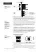
Starting Out Starting Out Chapter 1 Starting Out With The Watlow Series 965, A Microprocessor-Based Control Dual Control OutputPID or on/off, User Selectable Single Input Type J, K, T, N or S Thermocouple, RTD or Process Output 1 Heat or Cool Output 2 Heat, Cool, Alarm or None Figure 1 Series 965 Input and Output Overview Output 1 or 2 Percent Power Auto-tuning for Heat & Cool PID Settings General Description Welcome to the Watlow Series 965, a 1/16 DIN microprocessor-based temperature control.
Chapter 2 Installation Install and Wire the Series 965 1.77" to 1.79" (44.96mm to 45.47mm) Panel Cutout Your Panel Thickness NOTE: Measurements between panel cutouts are the minimum recommended. 0.06" to 0.38" (1.5 to 9.7 mm) 1.77" to 1.79" (44.96mm to 45.47mm) Figure 2 Series 965 Multiple Panel Cutout Dimensions 0.38" (9.65mm) Minimum 0.85" (20mm) Figure 3 Series 965 Dimensions 4.7" (119mm) 2.1" (53 mm) 4.1" (104mm) 1.76" (45mm) 0.40" (10mm) 1.
0 to 0.019 space (0 to 0.483 mm) Installation Panel Ridges Figure 4 Mounting, Case Side View & Collar Cross Section 4A Bezel Tabs Mounting Collar External Gasket 4B Teeth Mounting Collar Cross Section (notice the offset teeth on each tab) 4. While pressing the front of the case firmly against the panel, slide the mounting collar over the back of the control. The tabs on the collar must line up with the mounting ridges on the case for secure installation. See Figure 4A again.
Power Wiring How to Wire the Series 965 The Series 965 wiring is illustrated by model number option. Check the unit sticker on the control and compare your model number to those shown here and also the model number breakdown in the Appendix of this manual. All outputs are referenced to a de-energized state. The final wiring figure is a typical system example.
Input Wiring Sensor Installation Guidelines We suggest you mount the sensor at a location in your process or system where it reads an average temperature. Put the sensor as near as possible to the material or space you want to control. Air flow past this sensor should be moderate. The sensor should be thermally insulated from the sensor mounting. See Chapter 4 for more information on DIP switch location and orientation.
Input Wiring RTD, 2- or 3-wire There could be a + 2°F input error for every 1Ω of lead length resistance when using a 2-wire RTD. That resistance, when added to the RTD element resistance, will result in erroneous input to the instrument. To overcome this problem, use a 3-wire RTD sensor, which compensates for lead length resistance. When extension wire is used for a 3-wire RTD, all wires must have the same electrical resistance (i.e. same gauge, copper stranded, same length).
Output 1 Wiring Switched DC Output Model # 965A - 3 C - 00 . V+ unregulated 9 Figure 12 Switched dc Output Wiring V— 10 Internal Circuitry NOTE: When an external device with a nonisolated circuit common is connected to the 4-20mA or Switched dc output, you must use an isolated or ungrounded thermocouple. + 10 - External Load Mechanical Relay Without Contact Suppression, Form C, 5 Amp Model # 965A - 3 D - 00 .
Output 2 Wiring Switched DC Output Model # 965A - 3 C - 00 NOTE: For more information on alarms see page 24. . 6 + 7 - External Load Figure 16 Switched dc Output Wiring V+ unregulated 6 V— 7 Internal Circuitry Mechanical Relay Without Contact Suppression, Form C, 5 Amp Model # 965A - 3 D - 00 Figure 17 5 Amp Mechanical Relay Wiring . Fuse 1 NC 6 COM 7 NO L1 External Load L2 Customer Supplied Quencharc Solid-state Relay Without Contact Suppression, 0.
Wiring Example Ó WARNING: All wiring and fusing must conform to the National Electric Code NFPA70. Contact your local board for additional information. Failure to observe NEC safety guidelines could result in injury to personnel or damage to property. Figure 19 System Wiring Example ç CAUTION: Watlow mercury relay loads must have a unity power factor. For RESISTIVE LOADS ONLY.
Keys/Displays Chapter 3 How to Use the Keys and Displays After one minute with no key activations, the control reverts to the process value in the upper display and the set point in the lower display. Upper Display Red or green, 0.3" (8 mm) high, seven segment, four digit LED display, indicating either process, actual temperature, the operating parameter values or an open sensor. When powering up, the Process display will be blank for five seconds. This display can be blank by setting [`dSP] to [`SEt].
Setup Chapter 4 How To Set Up The Series 965 Setting up the Series 965 is a simple process. First set the DIP switches to match your input type. Refer to the orientation below and Page 16 for the In parameter. Next, configure the 965's features to your application in the Setup Menu, then enter values in the Operating Menu. Both tasks use the MODE key to move through the menus and the Up-arrow/Down-arrow keys to select data. Before entering information in the Setup menu, set the dFL parameter.
Setup Entering the Setup Menu The Setup Menu displays the parameters that configure the Series 965's features to your application. Enter the Setup Menu by pressing the Up-arrow and Down-arrow keys simultaneously for 3 seconds. The lower display shows the LOC parameter, and the upper display shows its current level. All keys are inactive until you release both keys. You can reach the LOC parameter from anywhere.
Setup Setup Parameters When you are at the top of the menu, the Series 965 displays the user level of operation in the upper display, and the LOC parameter in the lower display. Press the MODE key and the value of the next parameter appears in the upper display, and the parameter appears in the lower display. LOC NOTE: Set the LOC parameter value as the final step in programming the Series 965 controller to prevent locking yourself out of the Operations and Setup Menu during initial programming.
Setup Range High: Selects the high limit of the operating range. Also used to set the high end of the process input. 5.0VÎ (dc) and 20mA represent Range High (rH) for process input. The process input is linearly scaled between rL and rH. See the model number and specification information in the Appendix for your range values, or refer to Table 1 on Page 18. Range: Sensor range high to rL Default: High limit of sensor type/9999 for process input Output 1: Selects the action for the primary output.
Setup PL dSP Power Limiting: The power limiting function in % power for heat. Range: Dependent on output type. -100 to100 Default: 100 Display: Selects which displays are active or viewable. Five seconds after selected, the appropriate display goes blank. Press MODE, Up-arrow or Down-arrow to override this feature and cause the current value to be displayed for 5 seconds. Range: nor Normal displays Default: nor SEt Set Point - Lower display only Pro Process - Upper display only Table 1 Input Ranges.
Operation = Prompt appears or not according to control configuration. M 75 The upper display will always return to the process value after 1 minute without key strokes.
Operation ALO Alarm Low: Represents the low process alarm or low deviation alarm. This parameter will not appear if Ot 2 = no or Con. If Ot2 = dEA or dE: Range: -999 to 0 Default: -999 If Ot2 = PrA or Pr: Range: rL to AHI Default: rL AHI Alarm High: Represents the high process alarm or high deviation alarm. This parameter will not appear if Ot2 = no or Con.
Tuning Chapter 5 NOTE: Set the HSC parameter under the Setup Menu to 3°F/2°C before auto-tuning your control. How to Tune and Operate Auto-tuning (Heat and/or Cool) The Series 965 can automatically tune the PID parameters to fit the characteristics of your particular thermal system. The auto-tuning procedure operates on a thermal response value — slow, medium, or fast.
Tuning To start auto-tuning: 1. Press the MODE key until the AUt prompt appears in the data display. 2. Select a thermal response value, 1=slow, 2=medium, and 3=fast, using the Up-arrow/Down-arrow keys. A thermal response value of 2 satisfactorily tunes most thermal systems. 3. Press the MODE key. While the control is in the tuning mode, the lower display alternately displays the normal information and the prompt At. The time between alternations is 1 second. 4.
Tuning/Operation to minimize wear on the mechanical components. Experiment until the cycle time is consistent with the quality of control you want. Ct will not appear on units with a process output. 5. Rate/Derivative Adjustment: Increase rA/dE to 1.00 minute. Then raise set point by 20° to 30°F, or 11° to 17°C. Observe the system's approach to set point. If the load temperature overshoots set point, increase rA/dE to 2.00 minutes.
Auto/Man-Alarms Using Alarms NOTE: When the alarm output is deenergized, the NO contact is open in the alarm condition. The Series 965 has two alarm types, Process or Deviation. A process alarm sets an absolute temperature. When the process exceeds that absolute temperature limit an alarm occurs. The process alarm set points may be independently set high and low. Under the Setup Menu, select the type of alarm output with the Ot2 parameter.
Error Codes Alarm Silencing is available with the deviation alarm. When SIL is selected as "on," the operator must manually disable the alarm by pressing the A/M key once on initial power up (in either the latching or non-latching mode). Alarm silencing disables the alarm output relay. However, the L2 LED (also the lower display when Ot2 = dEA) shows an alarm condition until the process value is within the "safe" region of the deviation alarm band.
Error Codes Error Code Actions • Er 2, Er 6, Er 7 result in these conditions: • If operator access is LOC 0, 1 or 2 ... …and the control was in AUTO operation when the error occurred, it goes into manual (% power) operation. If the output power is less than 75% power, and a <5% change in power occurred within the last two minutes, the 965 switches into manual operation at the last automatic power level (bumpless transfer). If the control was in manual operation, it remains there.
Noise Guidelines Appendix 1 Noise and Installation Guidelines For wiring guidelines, refer to the IEEE Standard No. 518-1982, available from IEEE, Inc. 345 East 47th Street, New York, NY 10017. Noise Sources • Switches and relay contacts operating inductive loads such as motors, coils, solenoids, and relays, etc. • Thyristors or other semiconductor devices which are not zero crossover-fired (randomly-fired or phase angle-fired devices). • All welding machinery and heavy current carrying conductors.
Wiring Guide • Use twisted pair wire any time control circuit signals must travel over two feet, or when you bundle them parallel with other wires. • Select the size or gauge of wire by calculating the maximum circuit current and choosing the gauge meeting that requirement. Using greatly larger wire sizes than required generally increases the likelihood of electrostatic (capacitance) coupling of noise. • Eliminate ground loops in the entire control system.
Appendix 2 Calibration Calibration Before attempting to calibrate, make sure you read through the procedures carefully and have the proper equipment called for in each procedure. Make sure the DIP switches are in the proper position per input type. See Figure 21, Page 14. Entering the Calibration Menu In the Calibration Menu, various input signals must be supplied for the control to go through its auto calibration. The calibration menu can only be entered from the LOC parameter in the Setup Menu.
Calibration Restoring Factory Calibration The rSt parameter restores the factory calibration values to the Series 965. If you calibrate your control incorrectly, you have the option to default to the original values. Once you leave the CAL menu, the values are entered. 1. Press the Up-arrow/Down-arrow keys simultaneously for three seconds. The LOC parameter appears in the lower display. Continue holding the Uparrow/Down-arrow keys until the lower display reads CAL. 2.
T/C Calibration Thermocouple Field Calibration Procedure Equipment Required • • Type "J" Reference Compensator with reference junction at 32°F/0°C, or Type "J" Thermocouple Calibrator set at 32°F/0°C. Precision millivolt source, 0-50mV min. range, 0.01mV resolution Setup And Calibration 1. Connect the AC line voltage L1 and L2 to the proper terminals. 2. Connect the millivolt source to Terminal 5 Negative and Terminal 3 Positive on the Series 965 terminal strip. Use regular 20 - 24 gauge wire.
Process Input 0-5 Volt Input Field Calibration Procedure Equipment Required: NOTE: • Before calibration on an installed control, make sure all data and parameters are documented. See Setup and Operation Charts, Pages 18 and 20. Precision DC voltage source 0-5 volt minimum range with 0.001 volt resolution. Setup and Calibration 1. Connect the AC line voltage L1 and L2 to the proper terminals on the 965. 2. Connect the voltage/current source to Terminal 3 (+) and 5 (-) on the Series 965 terminal strip.
4-20mA Output 4-20mA Output Field Calibration Procedure Equipment Required: • • 300Ω, 1/2 watt 10% resistor. 4 - 1/2 digit Digital Multimeter. NOTE: Setup And Calibration 1. Connect the ac line voltage L1 and L2 to the proper terminals of the 965. See Chapter 2. Set the multimeter to measure current. 2. Connect the multimeter in series with the 300Ω resistor to Terminal 9 Positive and 10 Negative on the Series 965 terminal strip. Use regular 20 - 24 gauge wire. 3.
Glossary, A-P This glossary includes general thermal system control terms. Alarm: A condition, generated by a controller, indicating that the process has exceeded or fallen below the set or limit point. Droop: Difference in temperature between set point and stabilized process temperature. Alarm Silence: Disables the alarm relay output. Duty cycle: Percentage of "load on time" relative to total cycle time. Anti-reset: Control feature that inhibits automatic reset action outside the proportional band.
Glossary, D-P Glossary, P-Z PD control: Proportioning control with rate action. PI control: Proportioning control with auto-reset. PID control: Proportioning control with auto-reset and rate. Process variable: Thermal system element to be regulated, such as time, temperature, relative humidity, etc. Programmed display data: Displayed information which gives the operator/programmer the "programmed" or intended process information, i.e., intended set point, intended alarm limit, etc.
Index Index A Alarms 24 Wiring 11 Appendix 27 A/M key 13 Automatic Operation 13, 23 Auto-tuning 21 B Bumpless transfer 23 C Calibration 29 Calibration Offset 20 D DC Output 1 10 DC Output 2 11 Declaration of Conformity 40 Default Parameters Operation 20 Setup 18 Dimensions Faceplate 5 Panel Cutout 5 Sideview 5 DIP Switches 14 Displays 13, 17 Down-arrow key 13 E Eliminate Noise 28 Entering the Setup Menu 15 Error Codes 25 F, G General Description 4 Glossary 34 H High Voltage Wiring 7 Hysteresis 17 I Input Wi
Warranty Index Warranty The Watlow Series 965 is warranted to be free of defects in material and workmanship for 36 months after delivery to the first purchaser for use, providing that the units have not been misapplied. Since Watlow has no control over their use, and sometimes misuse, we cannot guarantee against failure.
Specifications Specifications—(1460) Control Mode • Microprocessor-based, user selectable control modes • Single input, dual output • 2.
Model No. Series 965 Model Number Information Ordering Information—W965-XMNN Rev A00 965A-3___-00__ Output 1 C = Switched dc output, non-isolated D = Electromechanical relay, Form C, 5A, without contact suppression1 3 F = Process, 4-20mAÎ (dc), non-isolated K = Solid-state relay, Form A, 0.5A, without contact suppression 3 Output 2 A = None C = Switched dc output, non-isolated D = Electromechanical relay, Form C, 5A, without contact suppression1 3 K = Solid-state relay, Form A, 0.
Conformity Put Declaration of Conformity on this page.
Series 965 Quick Reference Use this page as a quick reference for the Series 965. Tear along the perforation. Keys & Displays Upper Display: Red or green, LED display, indicating either process actual temperature, the operating parameter values, or an open sensor. L1: When lit it indicates Output 1 is energized. Lower Display: Red or green, four digit LED display, indicating the set point, output value, parameters for data in the upper display, or error and alarm codes. MN: Lit when in manual operation.
Entering the Setup Menu The Setup Menu displays the parameters that configure the Series 965's features to your applicaton. Enter the Setup menu by pressing the Up-arrow/Down-arrow keys simultaneously for 3 seconds. The lower display shows the LOC parameter, and the upper display shows its current level. All keys are inactive until you release both keys. You can reach the LOC parameter from anywhere. You will not see all parameters in these menus depending on your unit's configuration and model number.
Watlow Series 965 User's Manual Watlow Controls, 1241 Bundy Blvd., P.O.