EZ-ZONE PM ® User’s Guide PID Controller Models TOTAL CUSTOMER SATISFACTION 3 Year Warranty ISO 9001 Registered Company Winona, Minnesota USA 1241 Bundy Boulevard., Winona, Minnesota USA 55987 Phone: +1 (507) 454-5300, Fax: +1 (507) 452-4507 http://www.watlow.com 0600-0058-0000 Rev. N January 2015 Made in the U.S.A.
Safety Information Unit is a Listed device per Underwriters Laboratories®. It has been evaluated to United States and Canadian requirements for Hazardous Locations Class 1 Division II Groups A, B, C and D. ANSI/ISA 12.12.01-2007. File E184390 QUZW, QUZW7. See: www.ul.com We use note, caution and warning symbols throughout this book to draw your attention to important operational and safety information. A “NOTE” marks a short message to alert you to an important detail.
• Complete model number • All configuration information • User's Guide • Factory Page Return Material Authorization (RMA) 1. Call Watlow Customer Service, (507) 454-5300, for a Return Material Authorization (RMA) number before returning any item for repair. If you do not know why the product failed, contact an Application Engineer or Product Manager. All RMA’s require: • Ship-to address • Bill-to address • Contact name • Phone number • Method of return shipment • Your P.O.
TC Table of Contents Chapter 1: Overview . . . . . . . . . . . . . . . . . . . . . . . . . . . . . . . . . . . . . 3 Standard Features and Benefits . . . . . . . . . . . . . . . . . . . . . . . . . . . . . . . . 3 Getting Started Quickly. . . . . . . . . . . . . . . . . . . . . . . . . . . . . . . . . . . . . 5 Chapter 2: Install and Wire. . . . . . . . . . . . . . . . . . . . . . . .
TC Table of Contents (cont.) Chapter 7: Profiling Page. . . . . . . . . . . . . . . . . . . . . . . . . . . . . . . . . 74 Profile Setup. . . . . . . . . . . . . . . . . . . . . . . . . . . . . . . . . . . . . . . . . . . . . . 74 Starting a Profile. . . . . . . . . . . . . . . . . . . . . . . . . . . . . . . . . . . . . . . . . . . 75 Profiling Menu . . . . . . . . . . . . . .
1 Chapter 1: Overview The EZ-ZONE ® PM takes the pain out of solving your thermal loop requirements. Watlow’s EZ-ZONE PM controllers offer options to reduce system complexity and the cost of control-loop ownership. You can order the EZ-ZONE PM as a PID controller or an over-under limit controller, or you can combine both functions in the PM Integrated Limit Controller.
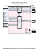
• Programmable EZ-Key enables simple one-touch operation of repetitive user activities Programmable Menu System • Reduces set up time and increases operator efficiency Full-featured Alarms • Improves operator recognition of system faults • Control of auxiliary devices Heat-Cool Operation • Provides application flexibility with accurate temperature and process control Profile Capability • Preprogrammed process control • Ramp and soak programming with four files and 40 total steps A Conceptual View of the PM
You can assign more than one output to respond to a single instance of a function. For example, alarm 2 could be used to trigger a light connected to output 1 and a siren connected to digital output 5. Input Events and Output Events Input and output events are internal states that are used exclusively by profiles. The source of an event input can come from a real-world digital input or an output from another function.
EZ-ZONE® PM PID Model System Diagram Universal Sensor Input, Configuration Communications, Red/Green 7-Segment Display Output Functions Input Functions Input sensor None Profile start/stop Profile start Profile hold/resume Profile disable TRU-TUNE+® disable Control outputs off Manual/auto mode Tune Idle set point Force alarm Loop & alarms off Silence alarm Alarm reset Lock keypad Restore user settings Network remote user interface, personal computer, programmable logic controller, humanmachine interfa
2 Dimensions Chapter 2: Install and Wire 1/32 DIN 15.9 mm 0.63 in 53.3 mm 2.10 in 101.6 mm 4.00 in 31.2 mm 1.23 in 30.9 mm 1.22 in Side Front Top 44.96 to 45.47 mm (1.77 to 1.79 inches) Recommended panel spacing 22.2 to 22.5 mm (0.87 to0.89 inches) panel thickness 1.53 to 9.52 mm (0.060 to 0.375) 21.6 mm (0.85 in) Minimum 21.6 mm (0.
1/16 DIN 15.8 mm (0.62 in) 101.6 mm (4.00 in) 53.3 mm (2.10 in) 53.3 mm (2.10 in) Side Front 51.2 mm (2.02 in) Top L1 L3 K1 K3 99 J1 J3 CF 98 L2 L4 CD K2 K4 CE T1 T2 B5 S1 S2 D6 R1 R2 D5 Back 44.96 to 45.47 mm (1.77 to 1.79 inches) 44.96 to 45.47 mm (1.77 to 1.79 inches) panel thickness 1.53 to 9.52 mm (0.060 to 0.375) 21.6 mm (0.85 in) Minimum 21.6 mm (0.
1/8 DIN (PM8) Vertical 15.75 mm (0.62 in) 1.52 mm (0.06 in) 53.34 mm (2.10 in) 100.33 mm (3.95 in) 10.16 mm (0.40 in) 30.73 mm (1.21 in) 54.86 mm (2.16 in) 101.60 mm (4.00 in) 1/8 DIN (PM8) Vertical Recommended Panel Spacing 44.96 to 45.60 mm (1.77 to 1.79 inches) 92.00 to 92.80 mm (3.62 to 3.65 inches) Panel thickness (0.060 in) 1.53 mm to (0.375 in) 9.52 mm 21.6 mm (0.85 in) Minimum 21.6 mm (0.
1/8 DIN (PM9) Horizontal 15.75 mm (0.62 in) 1.52 mm (0.06 in) 100.33 mm (3.95 in) 54.86 mm (2.16 in) 53.34 mm (2.10 in) 10.16 mm (0.40 in) 30.73 mm (1.21 in) 101.60 mm (4.00 in) 1/8 DIN (PM9) Horizontal Recommended Panel Spacing 92.00 to 92.80 mm (3.62 to 3.65 inches) 44.96 to 45.60 mm (1.77 to 1.79 inches) Panel thickness (0.060 in) 1.53 mm to (0.375 in) 9.52 mm 21.6 mm (0.85 in) Minimum 21.6 mm (0.
1/4 DIN (PM4) 15.75 mm (0.62 in) 1.52 mm (0.06 in) 100.33 mm (3.95 in) 100.33 mm (3.95 in) 12.70 mm (0.50 in) 30.73 mm (1.21 in) 100.84 mm (3.97 in) 1/4 DIN (PM4) Recommended Panel Spacing 92.0 to 93.0 mm (3.62 to 3.65 inches) 92.0 to 93.0 mm (3.62 to 3.65 inches) 21.6 mm (0.85 inches) Minimum Panel thickness .060 (1.53) to .375 (9.52) 21.6 mm (0.
Installation Don't be afraid to apply enough pressure to properly install the controller. The seal system is compressed more by mating the mounting collar tighter to the front panel (see pictures above). If you can move the case assembly back and forth in the cutout, you do not have a proper seal. The tabs on each side of the mounting collar have teeth that latch into the ridges on the sides of the controller.
Returning the Controller to its Case 1. Ensure that the orientation of the controller is correct and slide it back into the housing. Note: The controller is keyed so if it feels that it will not slide back in do not force it. Check the orientation again and reinsert after correcting. 2. Using your thumbs push on either side of the controller until both latches click. Chemical Compatibility This product is compatible with acids, weak alkalis, alcohols, gamma radiation and ultraviolet radiation.
Wiring Terminal Definitions for Slots A Slot A Output Terminal Function Configuration common (Any switched dc output can use this common.
Back View Slot Orientation 1/8 DIN Vertical PM8 Power A C E D B Dig I/O 5 & 6 485 Comms Dig I/O 5 & 6 485 Comms C Input 1 Input 1 E Output 2 Output 2 A Output 1 Output 1 Power Back View Slot Orientation 1/8 DIN Horizontal PM9 Input 1 A D E C Dig I/O 5 & 6 485 Comms Communications Card Output 2 Digital I/O 7 - 12 Output 1 D B Power Back View Slot Orientation 1/4 DIN Horizontal PM4 Output 3 Output 4 Input 2 B EZ-ZONE PM Isolation Blocks Digital Inputs & Outputs 5-6 No Iso
Warning: Óç Use National Electric (NEC) or other country-specific standard wiring and safety practices when wiring and connecting this controller to a power source and to electrical sensors or peripheral devices. Failure to do so may result in damage to equipment and property, and/or injury or loss of life. Low Power Slot C 98 99 Note: Adjacent terminals may be labeled differently, depending on the model number. Note: To prevent damage to the controller, do not connect wires to unused terminals.
Warning: Óç Input 1 Thermocouple Slot A Use National Electric (NEC) or other country-specific standard wiring and safety practices when wiring and connecting this controller to a power source and to electrical sensors or peripheral devices. Failure to do so may result in damage to equipment and property, and/or injury or loss of life. • • • • - Note: Maximum wire size termination and torque rating: • 0.0507 to 3.30 mm2 (30 to 12 AWG) single-wire termination or two 1.31 mm2 (16 AWG) • 0.56 Nm (5.0 lb.
Warning: Óç Input 1 Thermistor Slot A Use National Electric (NEC) or other country-specific standard wiring and safety practices when wiring and connecting this controller to a power source and to electrical sensors or peripheral devices. Failure to do so may result in damage to equipment and property, and/or injury or loss of life.
Warning: Óç DO5 Output Curve Volts mA 25.0 Use National Electric (NEC) or other country-specific standard wiring and safety practices when wiring and connecting this controller to a power source and to electrical sensors or peripheral devices. Failure to do so may result in damage to equipment and property, and/or injury or loss of life. 20.0 15.0 10.0 Note: Note: 5.
Warning: Óç Output 1 Switched DC/Open Collector Use National Electric (NEC) or other country-specific standard wiring and safety practices when wiring and connecting this controller to a power source and to electrical sensors or peripheral devices. Failure to do so may result in damage to equipment and property, and/or injury or loss of life. Slot A common Note: Maximum wire size termination and torque rating: • 0.0507 to 3.30 mm2 (30 to 12 AWG) single-wire termination or two 1.31 mm2 (16 AWG) • 0.
Warning: Óç Use National Electric (NEC) or other country-specific standard wiring and safety practices when wiring and connecting this controller to a power source and to electrical sensors or peripheral devices. Failure to do so may result in damage to equipment and property, and/or injury or loss of life. Output 1 Solid-State Relay, Form A Slot A normally open L1 common K1 Note: Maximum wire size termination and torque rating: • 0.0507 to 3.30 mm2 (30 to 12 AWG) single-wire termination or two 1.
Warning: Óç Use National Electric (NEC) or other country-specific standard wiring and safety practices when wiring and connecting this controller to a power source and to electrical sensors or peripheral devices. Failure to do so may result in damage to equipment and property, and/or injury or loss of life.
Warning: Óç Standard Bus EIA-485 Communications Slot C Use National Electric (NEC) or other country-specific standard wiring and safety practices when wiring and connecting this controller to a power source and to electrical sensors or peripheral devices. Failure to do so may result in damage to equipment and property, and/or injury or loss of life. 98 99 CF common CD CE D6 Maximum wire size termination and torque rating: • 0.0507 to 3.30 mm2 (30 to 12 AWG) single-wire termination or two 1.
Warning: Óç A Network Using Watlow's Standard Bus and an RUI/Gateway Power Supply EZ-ZONE ST ST_ _ - (B or F) _ M _ -_ _ _ _ Use National Electric (NEC) or other country-specific standard wiring and safety practices when wiring and connecting this controller to a power source and to electrical sensors or peripheral devices. Failure to do so may result in damage to equipment and property, and/or injury or loss of life.
Warning: Óç Connecting a Computer to PM Controls Using B&B 485 to USB Converter Address 2 Address 1 Use National Electric (NEC) or other country-specific standard wiring and safety practices when wiring and connecting this controller to a power source and to electrical sensors or peripheral devices. Failure to do so may result in damage to equipment and property, and/or injury or loss of life. USB Port Slot C Slot B Slot A Slot C Maximum wire size termination and torque rating: • 0.0507 to 3.
3 Chapter 3: Keys and Displays Upper (Left, 32nd DIN) Display: 1/32 DIN (PM3) In the Home Page, displays the process value, otherwise displays the value of the parameter in the lower display. Zone Display: Indicates the controller zone.
Responding to a Displayed Message An active message will cause the display to toggle between the normal settings and the active message in the upper display and [Attn] in the lower display. Your response will depend on the message and the controller settings. Some messages, such as Ramping and Tuning, indicate that a process is underway.
4 Chapter 4: Home Page Default Home Page Parameters Watlow’s patented user-defined menu system improves operational efficiency. The user-defined Home Page provides you with a shortcut to monitor or change the parameter values that you use most often. The default Home Page is shown on the following page. When a parameter normally located in the Setup Page or Operations Page is placed in the Home Page, it is accessible through both.
Modifying the Home Page Follow the steps below to modify the Home Page: 1. Push and hold the Advance ‰ key and the Infinity ˆ key for approximately six seconds. Upon entering the Factory Page the first menu will be the Custom Menu [Cust] . 2. Push the Advance ‰ key where the lower display will show [Cust] and the upper display will show [1] . 3. Push the Advance ‰ button where the prompt for the Process Value [aC; p u] will be displayed on top and Parameter [`par] in the bottom.
Modifying the Display Pairs The Home Page, being a customized list of as many as 20 parameters can be configured in pairs of up to 10 via the Display Pairs [d;prs] prompt found in the Diagnostic Menu [diag] (Factory Page). The listing in the table that follows is what one may typically find in the Home Page as defaults based on controller part numbers. It is important to note that some of the prompts shown may not appear simply because the feature is not being used or is turned off.
Home Page Defaults Home Page Display Parameter Page and Menu All Models 1 Active Process Value (1) Numerical value Operations Page, Monitor Menu 2 Active Set Point (1) Numerical value Operations Page, Monitor Menu 3 Control Mode (1) [C;M1] Operations Page, Monitor Menu 4 Heat Power (1) [h;pr1] Operations Page, Monitor Menu 5 Cool Power (1) [C;pr1] Operations Page, Monitor Menu 6 Autotune (1) [aut1] Operations Page, Loop Menu 7 Idle Set Point (1) [id;s1] Operations Page, Loop Me
Navigating the EZ-ZONE® PM PID Controller Applies to All Models - 1/16 DIN Shown Below ® ® ® ® [``Ai] [``70] [``70] [Cust] [`Set] [``72] [``72] [fCty] Home Page from anywhere: Press the Infinity Factory Page from Home Page: Press both the Advance ‰ and Infinity ˆ keys for six seconds. Key ˆ for two seconds to return to the Home Page. ® ® [``70] [``Ai] [``72] [oper] Operations Page from Home Page: Press both the Up ¿ and Down ¯ keys for three seconds.
Conventions Used in the Menu Pages To better understand the menu pages that follow review the naming conventions used. When encountered throughout this document, the word "default" implies as shipped from the factory. Each page (Operations, Setup, Profile and Factory) and their associated menus have identical headers defined below: Header Name Definition Display Visually displayed information from the control. Parameter Name Describes the function of the given parameter.
Range Within this column notice that on occasion there will be numbers found within parenthesis. This number represents the enumerated value for that particular selection. Range selections can be made simply by writing the enumerated value of choice using any of the available communications protocols. As an example, turn to the Setup Page and look at the Analog Input [``Ai] menu and then the Sensor Type [`Sen] prompt.
5 Chapter 5: Operations Page Navigating the Operations Page To navigate to the Operations Page, follow the steps below: 1. From the Home Page, press both the Up ¿ and Down ¯ keys for three seconds. [``Ai] will appear in the upper display and [oPEr] will appear in the lower display. 2. Press the Up ¿ or Down ¯ key to view available menus. 3. Press the Advance Key ‰ to enter the menu of choice. 4.
Operations Page Display Parameter Name Description Range Default Modbus Relative Address CIP Class Instance Attribute hex (dec) Instance 1 Map 1 Map 2 360 360 Data Type & Read/ Write Profibus Index Parameter ID 0x68 (104) 1 1 0 4001 float R [``Ai] [oPEr] Analog Input Menu [`Ain] [ Ain] Analog Input (1) Analog Input Value View the process value. Note: -1,999.000 to 9,999.000°F or units -1,128.000 to 5,537.
Operations Page Display Parameter Name Description Range [``o;u] [ o.v] Linearization (1) Output Value View the value of this function's output. -1,999.000 to 9,999.000°F or units -1,128.000 to 5,537.000°C No Display Linearization (1) Output Error View reported cause for Linearization output malfunction.
Operations Page Parameter Name Description Display Range Default Modbus Relative Address CIP Class Instance Attribute hex (dec) Profibus Index Parameter ID Data Type & Read/ Write [`dio] [oPEr] Digital Input/Output Menu [`do;S] [ do.S] Digital Output (5 to 6) Output State View the state of this output. [`off] Off (62) [``on] On (63) ---- Instance 5 Map 1 Map 2 1012 1132 Offset to next instance equals +30 0x6A (106) 5 to 6 7 90 6007 uint R [`di;S] [ di.
Operations Page Display Parameter Name Description Range Default Modbus Relative Address CIP Class Instance Attribute hex (dec) Profibus Index Parameter ID Data Type & Read/ Write No Display Monitor (1) -1,999.000 to Set Point Active 9,999.000°F or units Read the current active set -1,128.000 to point. 5,537.000°C ---- Instance 1 Map 1 Map 2 2172 2652 0x6B (107) 1 7 ---- 7018 float R No Display Monitor (1) Autotune Status Read the present status of Autotune.
Operations Page Display Parameter Name Description Range Default Modbus Relative Address CIP Class Instance Attribute hex (dec) Profibus Index Parameter ID Data Type & Read/ Write [`id;S] [ id.S] Control Loop (1) Idle Set Point Set a Set Point that can be triggered by an event state. Minimum Set Point to Maximum Set Point (Setup Page) 75.0°F or units 24.0°C Instance 1 Map 1 Map 2 2176 2656 0x6B (107) 1 9 50 7009 float RWES [`h;Pb] [ h.
Operations Page Parameter Name Description Display Range Default Modbus Relative Address CIP Class Instance Attribute hex (dec) Profibus Index Parameter ID Data Type & Read/ Write No Display Control Loop (1) Loop Error Open Loop detect deviation has been exceeded. [none] None (61) [`lp;o] Open Loop (1274) [`lp;r] Reversed Sensor (1275) ---- Instance 1 Map 1 Map 2 ---2408 0x6C (108) 1 0x30 (48) ---- 8030 uint R No Display Control Loop (1) Clear Loop Error Current state of limit output.
Operations Page Parameter Name Description Display No Display Alarm (1 to 4) Alarm Clearable Indicates if the alarm can be cleared.
Operations Page Display Parameter Name Description Range Default Modbus Relative Address CIP Class Instance Attribute hex (dec) Profibus Index Parameter ID Data Type & Read/ Write [`Su;C] [ Su.C] Timer Source Value C View the value of Source Function C. -1999.000 to 999.000°F or units -1110.555 to 5555.000 ---- Instance 1 Map 1 Map 2 ---8572 0x83 (109) 1 0x25 (37) ---- 31037 float R [`Su;d] [ Su.d] Timer Source Value D View the state of Source Function D.
Operations Page Display Parameter Name Description Range Default Modbus Relative Address CIP Class Instance Attribute hex (dec) Profibus Index Parameter ID Data Type & Read/ Write No Display Timer Timer Timing Indicates whether the timer is running. On (63) Off (62) ---- Instance 1 Map 1 Map 2 ---8528 0x83 (131) 1 0x0F (15) ---- 31015 uint R No Display Timer Output Error Indicates errors that may have interfered with the timer operation.
Operations Page Display Parameter Name Description Range Default Modbus Relative Address CIP Class Instance Attribute hex (dec) Profibus Index Parameter ID Data Type & Read/ Write [P;ACr] [PACr] Profile Status Action Request [nonE] None (61) [step] Step Start (89) [`End] Terminate (148) [rESU] Resume (147) [PAUS] Pause (146) [ProF] Profile (77) None Instance 1 Map 1 Map 2 2540 4360 0x7A (122) 1 0xB (11) 205 22011 uint RW [`StP] [ StP] Profile Status Step View the currently running step.
Operations Page Display Parameter Name Description Range Default Modbus Relative Address CIP Class Instance Attribute hex (dec) Profibus Index Parameter ID Data Type & Read/ Write [Ent2] [Ent2] Profile Status Event 2 View or change the event output states. [`off] Off (62) [``on] On (63) Off Instance 1 Map 1 Map 2 2548 4514 0x7A (122) 1 0xF (15) ---- 22015 uint RW [``JC] [ JC] Profile Status Jump Count Remaining View the jump counts remaining for the current loop.
6 Chapter 6: Setup Page Navigating the Setup Page To go to the Setup Page from the Home Page, press both the Up ¿ and Down ¯ keys for six seconds. [``Ai] will appear in the upper display and [`Set] will appear in the lower display. • Press the Up ¿ or Down ¯ key to view available menus. On the following pages top level menus are identified with a yellow background color. •Press the Advance Key ‰ to enter the menu of choice.
[`r;bS] Ready Band State [`rdY] Ready Band [t;For] Time Format [hoUr] Hours [Min] Minutes [`SEC] Seconds [Ct;SP] Closed Loop Timer Set Point [``St] Signal Time [otpt] [`Set] Output Menu [```1] [otpt] Output (1 to 2) [``Fn] Function [``Fi] Output Function Instance [`o;Ct] Time Base Type [`o;tb] Fixed Time Base [`o;Lo] Low Power Scale [`o;hi] High Power Scale [otpt] Output 1 process [`o;ty] Output Type [``Fn] Function [``Fi] Output Function Instance [`S;L
Setup Page Display CIP Modbus RelaClass tive Instance Address Attribute hex (dec) Data Type & Read/ Write Profibus Index Parameter ID Instance 1 0x68 (104) 1 Map 1 Map 2 5 368 368 3 4005 uint RWES [```b] B (11) [```H] K (48) J [```C] C (15) [```n] N (58) [```d] D (23) [```r] R (80) [```E] E (26) [```S] S (84) [```F] F (30) [```t] T (93) [```J] J (46) Instance 1 0x68 (104) 1 Map 1 Map 2 6 370 370 4 4006 uint RWES 2 Instance 1 0x68 (104) 1 Map 1 Map 2 7 372 372 ---- 4007 uint RWES Instance
Setup Page Display Parameter Name Description Range Default CIP Modbus RelaClass tive Instance Address Attribute hex (dec) Profibus Index Parameter ID Data Type & Read/ Write [`r;hi] [ r.hi] Analog Input (1) -1,999.000 to 9,999.000 Range High Set the high range for this function block's output. 9,999 Instance 1 0x68 (104) 1 Map 1 Map 2 0x12 (18) 394 394 9 4018 float RWES [`P;EE] [ P.EE] Analog Input (1) Process Error Enable Turn the Process Error Low feature on or off.
Setup Page Display [`Ain] [ Ain] Parameter Name Description Analog Input (1) Analog Input Value View the process value. Note: Range Default -1,999.000 to 9,999.000°F or units -1,128.000 to 5,537.
Setup Page Display Parameter Name Description Range Default CIP Modbus RelaClass tive Instance Address Attribute hex (dec) Profibus Index Parameter ID Data Type & Read/ Write [`oP;2] [ op.2] Linearization (1) Output Point 2 Set the value that will be mapped to input 2. -1,999.000 to 9,999.000 1.0 Instance 1 0x86 (134) 1 Map 1 Map 2 ---3596 0x13 (19) 160 34019 float RWES [`iP;3] [ ip.3] Linearization (1) Input Point 3 Set the value that will be mapped to output 3. -1,999.000 to 9,999.
Setup Page Display Parameter Name Description Range Default CIP Modbus RelaClass tive Instance Address Attribute hex (dec) Profibus Index Parameter ID Data Type & Read/ Write [`iP;9] [ ip.9] Linearization (1) Input Point 9 Set the value that will be mapped to output 9. -1,999.000 to 9,999.000 8.0 Instance 1 0x86 (134) 1 Map 1 Map 2 ---3590 0x10 (16) 173 34016 float RWES [`oP;9] [ op.9] Linearization (1) Output Point 9 Set the value that will be mapped to input 9. -1,999.000 to 9,999.
Setup Page Display Parameter Name Description Range Default CIP Modbus RelaClass tive Instance Address Attribute hex (dec) Data Type & Read/ Write Profibus Index Parameter ID 82 6001 uint RWES 83 6005 uint RWES 84 6006 uint RWES 85 6002 uint RWES [`dio] [`Set] Digital Input/Output Menu [`dir] [ dir] [``Fn] [ Fn] [``Fi] [ Fi] [`o;Ct] [ o.
Setup Page Display [`o;tb] [ o.tb] Parameter Name Description Digital Output (5 to 6) Fixed Time Base Set the time base for fixed-time-base control. Range Default 0.1 to 60.0 1.
Setup Page Display [``Fn] [ Fn] Parameter Name Description Digital Input (5 to 6) Action Function Select the function that will be triggered by a true state for Digital Input 5 and or 6.
Setup Page Display Parameter Name Description Range Default CIP Modbus RelaClass tive Instance Address Attribute hex (dec) Profibus Index Parameter ID Data Type & Read/ Write [`C;Ag] [ C.Ag] Control Loop (1) Cool Algorithm Set the cool control method. [`oFF] Off (62) [`Pid] PID (71) [on;of] On-Off (64) Off Instance 1 0x97 (151) 1 Map 1 Map 2 4 1886 2366 73 8004 uint RWES [`C;Cr] [ C.Cr] Control Loop (1) Cool Output Curve Select a cool output curve to change the responsiveness of the system.
Setup Page CIP Modbus RelaClass tive Instance Address Attribute hex (dec) Parameter ID 71 8008 float RWES Instance 1 0x97 (151) 1 Map 1 Map 2 0x10 (16) 1910 2390 ---- 8022 uint RWES 0 Instance 1 0x97 (151) 1 Map 1 Map 2 1912 2392 0x11 (17) ---- 8034 uint RWES 3 Instance 1 0x97 (151) 1 Map 1 Map 2 1914 2394 0x12 (18) ---- 8035 uint RWES 90.
Setup Page Display Parameter Name Description Range Default CIP Modbus RelaClass tive Instance Address Attribute hex (dec) Profibus Index Parameter ID Data Type & Read/ Write [`UFA] [UFA] Control Loop (1) User [`oFF] Off, sets output Auto-to-Manual Power power to 0% (62) Select what the controller [bPLS] Bumpless Transfer, outputs will do when the maintains same output user switches control to power, if it was less than manual mode.
Setup Page Display Parameter Name Description Range Default CIP Modbus RelaClass tive Instance Address Attribute hex (dec) Profibus Index Parameter ID Data Type & Read/ Write [`L;dt] [ L.dt] Control Loop (1) 0 to 3,600 seconds Open Loop Detect Time The Open Loop Detect Deviation value must occur for this time period to trigger an open-loop error. Process must deviate by the Open Loop Detect Deviation value in this specified time while at 100% PID to prevent an open loop error.
Setup Page Default CIP Modbus RelaClass tive Instance Address Attribute hex (dec) Minimum Set Point to Maximum Set Point (Setup Page) 75.0°F or units 24.0°C Instance 1 Map 1 Map 2 2160 2640 0x6B (107) 1 1 49 7001 float RWES Control Loop (1) Idle Set Point Set a Set Point that can be triggered by an event state. Minimum Set Point to Maximum Set Point (Setup Page) 75.0°F or units 24.0°C Instance 1 Map 1 Map 2 2176 2656 0x6B (107) 1 9 50 7009 float RWES [SP;Lo] [SP.
Setup Page Display [``Fi] [ Fi] [`o;Ct] [ o.Ct] [`o;tb] [ o.tb] [`o;Lo] [ o.Lo] [`o;hi] [ o.hi] [`o;ty] [ o.ty] Parameter Name Description Range Default CIP Modbus RelaClass tive Instance Address Attribute hex (dec) Instance 1 0x6A (106) 1 to 2 Map 1 Map 2 6 890 1010 Output Digital (1 to 2) Output Function Instance Set the instance of the function selected above. 1 to 2 1 Output Digital (1 to 2) Time Base Type Set the Time Base Type type.
Setup Page Display Parameter Name Description Range Default CIP Modbus RelaClass tive Instance Address Attribute hex (dec) Profibus Index Parameter ID Data Type & Read/ Write [``Fn] [ Fn] Output Process (1) Output Function Set the type of function that will drive this output.
Setup Page Display Parameter Name Description Range Default CIP Modbus RelaClass tive Instance Address Attribute hex (dec) Profibus Index Parameter ID Data Type & Read/ Write [`r;hi] [ r.hi] Output Process (1) -1,999.000 to 9,999.000°F Range High or units Set the maximum value -1,128.000 to 5,537.000°C of the retransmit value range in process units. When the retransmit source is at this value, the retransmit output will be at its Scale High value.
Setup Page Display [`A;Sd] [ A.Sd] Parameter Name Description Range Default Data Type & Read/ Write Profibus Index Parameter ID 26 9004 uint RWES 0x6D (109) 1 to 4 2 18 9002 float RWES 0x6D (109) 1 to 4 1 19 9001 float RWES 27 9007 uint RWES 28 9008 uint RWES Instance 1 0x6D (109) 1 to 4 Map 1 Map 2 4 1486 1886 Both Alarm (1 to 4) [both] Both (13) Sides [high] High (37) Select which side or sides [LoW] Low (53) will trigger this alarm.
Setup Page Display [`A;Si] [ A.Si] [A;dSP] [A.dSP] Parameter Name Description Range Default Alarm (1 to 4) [`oFF] Off (62) Silencing [``on] On (63) Turn Silencing on to allow the user to disable this alarm. Off Alarm (1 to 4) [`oFF] Off (62) Display [``on] On (63) Display an alarm message when an alarm is active.
Setup Page Display [`A;St] [`A.St] Parameter Name Description Range Default ---- Alarm (1 to 4) [`Str] Startup (88) Alarm State [nonE] None (61) Display the alarm state in [`blo] Blocked (12) the Home Page.
Setup Page Display Parameter Name Description Range Default ---- CIP Modbus RelaClass tive Instance Address Attribute hex (dec) Data Type & Read/ Write Profibus Index Parameter ID Instance 1 0x83 (131) 1 Map 1 Map 2 ---8542 0x16 (22) ---- 31022 uint R [`r;bS] [ r.bS] Timer Ready Band State Display whether the process value is in the ready band. [`rdY] [ rdY] Timer 0.000 to 9999.000°F or Ready Band units Set the how close the pro- 0.000 to 5555.
Setup Page Display [``Fn] [ Fn] Parameter Name Description Function Key (1 to 2) Action Function Program the EZ Key to trigger an action. Functions respond to a level state change or an edge level change.
Setup Page Display Parameter Name Description Range Default CIP Modbus RelaClass tive Instance Address Attribute hex (dec) Profibus Index Parameter ID Data Type & Read/ Write Ramp Time Instance 1 0x7A (122) 1 Map 1 Map 2 ---4414 0x26 (38) ---- 22038 uint RWE Global [StPt] Set Point (85) Profile Type [`Pro] Process (75) Set the profile startup to be based on a set point or a process value.
Setup Page Display Parameter Name Description Range Default CIP Modbus RelaClass tive Instance Address Attribute hex (dec) ---- ---- Parameter ID ---- Data Type & Read/ Write [sutb] [Sutb] Global -2.00 to 2.00 Percent Synchronized Variable Time Base Used to acquire tighter accuracy when running a profile or using the Timer feature. A setting of +0.01 would equate to approximately +9 seconds/day (faster) where a setting of -0.01 would equate to approximately -9 seconds/day (slower). 0.
Setup Page Display Parameter Name Description Range Default CIP Modbus RelaClass tive Instance Address Attribute hex (dec) Profibus Index Parameter ID Data Type & Read/ Write [`Ad;S] [ Ad.S] Communications 1 to 16 Standard Bus Address Set the network address of this controller. Each device on the network must have a unique address. The Zone Display on the front panel will display this number. 1 Instance 1 0x96 (150) 1 Map 1 Map 2 1 2480 2960 ---- 17001 uint RWE [Ad;M] [Ad.
Setup Page Display Parameter Name Description Range Default CIP Modbus RelaClass tive Instance Address Attribute hex (dec) Profibus Index Parameter ID Data Type & Read/ Write [rtC] (Available with PM4, PM8 and PM9 models only) [`SEt] Real Time Clock Menu [hoUr] [hoUr] Real Time Clock Hours Set the current time. 0 to 23 0 Instance 1 0x88 (136) 1 Map 1 Map 2 3 ---4004 ---- 36003 uint RW [Min] [Min] Real Time Clock Minutes Set the current time.
7 Chapter 7: Profiling Page Navigating the Profiling Page Note: Some of these menus and parameters may not appear, depending on the controller's options. See model number information in the Appendix for more information. If there is only one instance of a menu, no submenus will appear. Profile Setup First, consider some foundational profile setup features that once configured, will apply to all configured profiles.
2. Press the Up ¿ or Down ¯ key to change to another profile (1 to 4). 3. Press the Advance Key ‰ to move to the selected profiles first step. 4. Press the Up ¿ or Down ¯ keys to move through and select the step type. 5. Press the Advance Key ‰ to move through the se- lected step settings. 6. Press the Up ¿ or Down ¯ keys to change the steps settings. 7. Press the Infinity Key ˆ at any time to return to the step number prompt. 8. Press the Infinity Key ˆ again to return to the profile number prompt.
Configuring a Digital Input to Start and Stop a Profile 1. Navigate to the Setup Page and then the Digital I/O menu. From the Home Page, press and hold the ¿ or Down ¯ key for approximately six seconds where the upper display will show [``ai] and the lower display will show [`set] . 2. Press the Up ¿ or Down ¯ key to navigate to the Digital I/O menu. Upper display will show [`dio] and the lower display will show [`set] . 3.
1. Navigate to the Operations Page and then the Profile Status menu. From the Home Page, press and hold the ¿ or Down ¯ key for approximately three seconds where the upper display will show [``ai] and the lower display will show [oper] . 2. Press the Up ¿ or Down ¯ key to navigate to the Profile Status [ p ; s ta] menu. 3. Press the Advance Key will show [ p ; s tr] . ‰ to enter this menu. The upper display will show [```1] and the lower display 4.
Profiling Page Display Parameter Name Description Range Default Modbus Relative Address ---- ---- CIP Class ParamInstance eter ID Attribute hex (dec) Data Type & Read/ Write [``P1] [prof] Profiling Menu [``p1] [ P1] to [``p4] [ P4] Profile [1 to 4] Step Select a step to edit or view. [S;typ] [S.typ] Step Type Select a step type. [t;SP1] [t.
Profiling Page Display [rate] [rAtE] [W;P1] [W.P1] [WE;1] [WE.1] Parameter Name Description Step Type Parameters Ramp Rate When Step Type is Ramp Rate, enter the rate for ramping in degrees or units per minute. Range Default 0 to 9,999.000°F or units per minute 0 to 5,555.000°C per minute 0.0°F or units -18.0°C Step Type Parameters Wait Event 2 When Step Type is Wait for Event or Wait For Both, select the event state that must be satisfied during this step.
Profiling Page Display [~~JS] [ JS] [~~JC] [ JC] [~End] [ End] Parameter Name Description Range Default Step Type Parameters Jump Step When Step Type is Jump, this setting specifies which step to jump back to. Jump Step must be a lower step number than the current step number. 1 to 40 Step Type Parameters Jump Count When Step Type is Jump, this specifies the number of jumps to repeat. A value of 0 creates an infinite loop. Loops can be nested four deep.
Display Step Type Description Parameters in Step Type ---- [UStP] [UStP] Step Types Unused Step This is an empty step that can be used to plan for future steps to be inserted or temporarily deactivate a step in a profile. Change step type back when the step should be active again. [``ti] [ ti] Step Types Ramp Time If Ramping Type in the Global Menu of the Setup Page is set for Ramp Time, the state of up to 2 event outputs may be set or maintained.
8 Chapter 8: Factory Page Navigating the Factory Page To go to the Factory Page from the Home Page, press and hold both the Advance ‰ and Infinity ˆ keys for six seconds. • Press the Advance Key ‰ to enter the menu of choice. • If a submenu exists (more than one instance), press the Up ¿ or Down ¯ key to select and then press the Advance Key ‰ to enter. • Press the Up ¿ or Down ¯ key to move through available menu prompts.
Factory Page Display Parameter Name Description Range Default Modbus Relative Address CIP Data Class Type Profibus ParamInstance & Index eter ID Attribute Read/ hex (dec) Write [Cust] [fcty] Custom Menu [`par] [ Par] Custom Parameter 1 to 20 Select the parameters that will appear in the Home Page. The Parameter 1 value will appear in the upper display of the Home Page. It cannot be changed with the Up and Down Keys in the Home Page.
Factory Page Display Parameter Name Description Range Default Modbus Relative Address CIP Data Class Type Profibus ParamInstance & Index eter ID Attribute Read/ hex (dec) Write [LoC;P] [LoC.P] Security Setting Profiling Page Change the security level of the Profiling Page. 1 to 3 3 ---- ---- ---- 3008 uint RWE [pas;e] [LoC.P] Security Setting Password Enable Set to on to require a password for menu changes.
Factory Page Display Parameter Name Description [pas;a] [PAS.A] Security Setting Administrator Password Used to acquire full access to all menus including disabling or changing passwords.
Factory Page Display Parameter Name Description No Display Diagnostics Firmware ID Display the Firmware ID.
9 Chapter 9: Features Changing PM PID Model Number to PM User Mode. . . . . . . . . . . . . . . 88 How to Change the PM Control Model Number to User Mode. . . . . . . . 89 How to Restore Original Factory Mode PM Model Number. . . . . . . . . . 89 Saving and Restoring User Settings. . . . . . . . . . . . . . . . . . . . . . . . . . 89 Programming the Home Page. . . . . . . . . . . . . . . . . . . . . . . . . . . . . .
Changing PM PID Model Number to PM User Mode EZ-ZONE PM PID firmware revisions of 13 and above allow the user to switch between a PM PID control to a PM Express PID. Switching to a PM Express PID eliminates the complexity of the PM PID control by allowing the user to operate with a simplified menu structure. Note: When switching from a PID control to an Express version, optional PM hardware (even though installed) and firmware features not available in a PM Express will no longer work.
How to Change the PM Control Model Number to User Mode 1. Enter Factory Page [FCty], Calibration Menu [`CAL] via front panel by pressing the Infinity ˆ or Reset Key and the Advance Key ‰ together or using EZ-ZONE Configurator software. 2. Once there, use the Advance Key ‰ to navigate to the Part Number [``Pn] prompt (green display). The red display will show factory [fCtY] indicating the factory model number as shown on the decal located on the side of the control is currently in effect. 3.
Programming the Home Page Watlow’s patented user-defined menu system improves operational efficiency. The user-defined Home Page provides you with a shortcut to monitor or change the parameter values that you use most often. You can create your own Home Page with as many as 20 of the active parameters. When a parameter normally located in the Setup Page or Operations Page is placed in the Home Page, it is accessible through both.
Manual Tuning In some applications, the autotune process may not provide PID parameters for the process characteristics you desire. If that is the case, you may want to tune the controller manually. 1. Apply power to the controller and establish a set point typically used in your process. 2. Go to the Operations Page, Loop Menu, and set Heat Proportional Band [`h;Pb] and/or Cool Proportional Band [`C;Pb] to 5. Set Time Integral [``ti] to 0. Set Time Derivative [``td] to 0. 3.
Before Tuning Before autotuning, the controller hardware must be installed correctly, and these basic configuration parameters must be set: • Sensor Type [`SEn] (Setup Page, Analog Input Menu), and scaling, if required; • Function [``Fn] (Setup Page, Output Menu) and scaling, if required. How to Autotune a Loop 1. Enter the desired set point or one that is in the middle of the expected range of set points that you want to tune for. 2. Disable TRU-TUNE+ ®. 3. Initiate an autotune.
liamperes or resistance depending on the sensor type to be calibrated. Use copper wire only to connect the precision source to the controller’s input. Keep leads between the precision source and controller as short as possible to minimize error. Use a precision volt/ohm meter capable of reading values to 4 decimal places or better. Prior to calibration, connect this volt/ohm meter to the precision source to verify accuracy.
Calibration of Analog Inputs: (cont.) 15. Validate calibration process by utilizing a calibrator to the analog input. 16. Enter calibration offset as recorded in step 2 if required to compensate for sensor error. Setting Electrical Input Slope [ELi;S] to 1.000 and Electrical Input Offset [ELi; o ] to 0.000, restores factory calibration as shipped from factory. Filter Time Constant Filtering smoothes an input signal by applying a first-order filter time constant to the signal.
Scale High and Scale Low (cont.) to 20 mA, 0 to 5V, 1 to 5V and 0 to 10V. You can create a scale range representing other units for special applications. You can reverse scales from high values to low values for analog input signals that have a reversed action. For example, if 50 psi causes a 4 mA signal and 10 psi causes a 20 mA signal. Scale low and high low values do not have to match the bounds of the measurement range.
Duplex (cont.) Outputs 1 and 3 can be ordered as process outputs. Select duplex [dUPL] as the Output Function [``Fn] (Setup Page, Output Menu). Set the output to volts [uoLt] or milliamps [`MA] with Output Type [`o;ty]. Set the range of the process output with Scale Low [`S;Lo] and Scale High [`S;hi]. NO-ARC Relay A NO-ARC relay provides a significant improvement in the life of the output relay over conventional relays.
Cool Output Curve A nonlinear output curve may improve performance when the response of the output device is nonlinear. If a cool output uses one of the nonlinear curves a PID calculation yields a lower actual output level than a linear output would provide. These output curves are used in plastics extruder applications: curve A for oil-cooled extruders and curve B for water-cooled extruders. Select a nonlinear cool output curve with Cool Output Curve [`C;Cr] (Setup Menu, Loop Menu).
Auto (closed loop) and Manual (open loop) Control (cont.) Power Temperature Bumpless transfer will allow the controller to transfer to the manual mode using the last power value calculated in the auto mode if the process had stabilized at a ±5 percent output power level for the time interval of Time Integral or 10 Actual Temperature Set Point seconds, whichever is longer, (Operations Page, Loop) prior to sensor failure, and that Sensor power level is less than 75 percent.
On-Off Control (cont.) Note: Input Error Power Mode [faIl] does not function in on-off control mode. The output goes off. The cooling action switches on when the process temperature rises above the set point plus the hysteresis. Temperature The cooling action switches on at startup. Process Temperature Hysteresis Set Point The cooling action switches off when the process temperature drops below the set point.
Proportional plus Integral (PI) Control The droop caused by proportional control can be corrected by adding integral (reset) control. When the system settles down, the integral value is tuned to bring the temperature or process value closer to the set point. Integral determines the speed of the correction, but this may increase the overshoot at startup or when the set point is changed. Too much integral action will make the system unstable.
Dead Band (cont.) When the dead band value is zero, the heating output activates when the temperature drops below the set point, and the cooling output switches on when the temperature exceeds the set point. Cool Output Active Set Point Temperature Heat Output Active Zero Dead Band Time When the dead band value is a negative value, both heating and cooling outputs are active when the temperature is near the set point.
Variable Time Base (cont.) The combination of variable time base output and a solid-state relay can inexpensively approach the effect of analog, phase-angle fired control. 50 percent output 100 percent output 3 ON, 3 OFF 10 ON, 0 OFF Select the AC Line Frequency [AC;LF] (Setup Page, Global Menu), 50 or 60 Hz. 66 percent output 6 ON, 3 OFF Single Set Point Ramping Ramping protects materials and systems that cannot tolerate rapid temperature changes.
b. Ready Band [`rdy ] , the set point changes and when the temperature is within ready band, the ready band indicator ‰ lights up and the countdown timer starts and continues as long as the temperature is within the ready band. When Time Remaining [`t;r1] equals zero, the set point changes from Closed Loop Timer Set Point [Ct;s1] back to Set Point [C;sp1]. A flashing colon [00; º0] indicates that a countdown is in progress. c.
If Source [```1] [```2] [```6] [```7] [```8] [`si;a] Function A of previous step is set to Function Key [`fUn] : EZ1 Key EZ2 Key Hold infinity key for 2 seconds Infinity ˆ and Down arrow ¯ Infinity ˆ and Up arrow ¿ Source Instance A 8. Advance ‰ to Source Function C [sfn;C] to select the analog source for the ready band. Use the up arrow ¿ to select from the options below: [``pu] Process Value [nonE] None [``ai] Analog Input [`Lnr] Linearization 9.
Alarms Alarms are activated when the output level, process value or temperature leaves a defined range. A user can configure how and when an alarm is triggered, what action it takes and whether it turns off automatically when the alarm condition is over. Configure alarm outputs in the Setup Page before setting alarm set points. Alarms do not have to be assigned to an output. Alarms can be monitored and controlled through the front panel or by using software.
Page, Alarm Menu). Alarm Silencing If Silencing is on the operator can disable the alarm output while the controller is in an alarm state. The process value or temperature has to enter the normal operating range beyond the hysteresis zone to activate the alarm output function again. An active message, such as an alarm message, will cause the display to toggle between the normal settings and the active message in the upper display and [Attn] in the lower display.
Using Lockout and Password Security If unintentional changes to parameter settings might raise safety concerns or lead to downtime, you can use the lockout feature to make them more secure. There are two methods of lockout that can be deployed, both of which are accessible from the Factory Page. Method 1- Change the value of the Read Lock [rloc] (1 to 5) and Set Lock [sloc] (0 to 5) prompts where the higher the value or setting for each translates to a higher security clearance (greater access).
Lockout Security [SLoC] & [rloC] Factory Page Menus Security Level Menus 0 1 2 3 4 5 Custom Menu N N N N N Y Lockout Menu* Y Y Y Y Y Y Diagnostic Menu** N Y Y Y Y Y Calibration Menu N N N N N Y * Using lockout Method 1 with [SLoC] set to 0, all writable parameters within the control will be inhibited (not writable) with two exceptions, [sloC] and [rloC] . As shown below, both of these parameters can always be seen and modified.
of access to the control. Back out of this menu by pushing the Infinity ˆ key. Once out of the menu, the Password Security will be enabled. How to Acquire Access to the Control To acquire access to any inaccessible Pages or Menus, go to the Factory Page and enter the [UloC] menu. Once there follow the steps below: Note: If Password Security (Password Enabled [pas;e] is On) is enabled the two prompts mentioned below in the first step will not be visible.
Assembly Definition Addresses - Fixed addresses used to define the parameter that will be stored in the "Working Addresses", which may also be referred to as a pointer. The value stored in these addresses will reflect (point to) the Modbus address of a parameter within the PM controller. Assembly Working Addresses - Fixed addresses directly related to their associated "Assembly Definition Addresses" (i.e.
The "Advanced" button allows the user to determine how many devices to look for on the network (1 to 17). After clicking on the "Next" button, the software will scan the network for the zone addresses specified while showing the progress made (as shown in the graphic below. When complete the software will display all of the available devices found on the network as shown below. The PM8 is shown highlighted to bring greater clarity to the control in focus.
Although the PM control now contains the configuration (because the previous discussion focused on doing the configuration on-line) it is suggested that after the configuration process is completed that the user save this file on the PC for future use. If for some reason someone inadvertently changed a setting without understanding the impact, it would be easy and perhaps faster to download a saved configuration back to the control versus trying to figure out what was changed.
Chapter 10: Appendix Troubleshooting Alarms, Errors and Control Issues Indication Description Possible Causes Alarm won’t clear or reset Alarm will not clear or reset with keypad or digital input • Latching is active Alarm won’t occur Alarm will not activate output • Silencing is active • Blocking is active • Alarm is set to incorrect output • Alarm is set to incorrect source • Alarm set point is incorrect Corrective Action • Reset alarm when process is within range or disable latching • Alarm set
Troubleshooting Alarms, Errors and Control Issues (cont.) Indication Description Possible Causes [LP;o1] Loop Open Error Open Loop Detect is active and the process value did not deviate by a user-selected value in a user specified period.
Troubleshooting Alarms, Errors and Control Issues (cont.) Indication Description Possible Causes Process doesn’t control to set point Process is unstable or never reaches set point • Controller not tuned correctly Temperature runway Process value continues to increase or decrease past set point.
Troubleshooting Alarms, Errors and Control Issues (cont.) Detection of and Rules Around Abnormal Sensor Conditions Inputs Detection of Abnormal Conditions Thermocouple Shorted No direct detection, Open loop firmware detection.
Modbus - Programmable Memory Blocks Assembly Definition Addresses and Assembly Working Addresses Assembly Definition Addresses 40 & 41 42 & 43 44 & 45 46 & 47 48 & 49 50 & 51 52 & 53 54 & 55 56 & 57 58 & 59 60 & 61 62 & 63 64 & 65 66 & 67 68 & 69 70 & 71 72 & 73 74 & 75 76 & 77 78 & 79 Assembly Working Addresses 200 & 201 202 & 203 204 & 205 206 & 207 208 & 209 210 & 211 212 & 213 214 & 215 216 & 217 218 & 219 220 & 221 222 & 223 224 & 225 226 & 227 228 & 229 230 & 231 232 & 233 234 & 235 236 & 237 238 & 2
Modbus Default Assembly Structure 80-119 Assembly Definition Addresses Default Pointers Assembly Working Addresses Assembly Definition Registers Default Pointers Assembly Working Registers Registers 80 & 81 Registers 240 & 241 Registers 100 & 101 Registers 260 & 261 Pointer 21 = 360 & 361 Analog Input 1 Process Value Registers 82 & 83 Pointer 22 = 362 & 363 Analog Input 1 Error Status Registers 84 & 85 Pointer 23 = 440 & 441 Analog Input 2 Process Value Registers 86 & 87 Pointer 24 = 442 & 443 Anal
Specifications LineVoltage/Power (Minimum /Maximum Ratings) •85 to 264V~ (ac), 47 to 63Hz •20 to 28VÅ (ac), 47 to 63Hz •12 to 40VÎ (dc) •14VA maximum power consumption (PM4, 8 & 9) •10VAmaximum power consumption (PM3 & 6) •Data retention upon power failure via nonvolatile memory •Compliant with SEMIF47-0200, FigureR1-1 voltage sag requirements @24V ~ (ac) or higher Environment Voltage Input Ranges - Accuracy ±10mV ±1 LSD at standard conditions - Temperature stability ±100 PPM/°C maximum Milliamp Inp
•Switched dc/open collector = 30VÎ (dc) max. @ 100mA max. current sink •Solid state relay (SSR), FormA, 0.5A @ 24VÅ (ac) min., 264V Å (ac) max., opto-isolated, without contact suppression, 20 VA 120/240VÅ (ac) pilot duty •Electromechanical relay, FormC, 5A, 24 to 240VÅ (ac) or 30VÎ (dc)max., resistive load, 100,000 cycles at rated load, 125 VA pilot duty at 120/240VÅ (ac), 25 VA at 24VÅ (ac) •Electromechanical relay, FormA, 5A, 24 to 240VÅ (ac) or 30VÎ (dc) max.
Ordering Information for PID Controller Models P M __ __ __ __ __ - __ A A A __ __ __ Controller EZ-ZONE® PID Controller Models TRU-TUNE+® Adaptive Tune, red-green 7-segment displays Package Size 3 6 8 9 4 Panel Mount 1/32 DIN Panel Mount 1⁄16 DIN Panel Mount 1⁄8 DIN Vertical Panel Mount 1⁄8 DIN Horizontal Panel Mount 1⁄4 DIN Horizontal Primary Function C R T B PID Controller with Universal Input PID Controller with Universal Input and Profiling Ramp and Soak PID Controller with Universal Input and Ti
Index Symbols [`A;bL] Alarm Blocking 66, 107 [AC;LF] AC Line Frequency 70, 103 [aC;sp] Produced Set Point 1 46 [`A;dL] Alarm Delay 67 [Ad;M] Modbus Address 73 [`Ad;S] Standard Bus Address 73 [A;dSP] Alarm Display 67, 68 [`A;hi] Alarm High Set Point 42, 66, 106 [`A;hy] Alarm Hysteresis 65, 106 [``Ai] Analog Input Menu 37, 50 [`Ain] Analog Input Value 52 [`A;LA] Alarm Latching 66, 106 [AL;E1] [AL;E2] [AL;E3] [AL;E4] Alarm Error 1 to 4 28 [`A;Lg] Alarm Logic 65 [AL;h1] [AL;h2] [AL;h3] [AL;h4] Alarm High 1 to 4
[otPt] Output Menu 62 [`o;ty] Output Type 63, 97 [``o;u] Output Value 38 [P;ACr] Action Request 46 [`PAr] Parity 73 [pas;a] Administrator Password 83, 86 [pas;e] Password Enable 83, 85 [PASS] Password 83, 86 [pas;u] User Password 83, 85 [PCoL] Protocol 72 [`p;dl] Peltier Delay 59 [`P;EE] Process Error Enable 51 [`P;EL] Process Error Low 51 [``Pn] Part Number 86, 87 [poti] Power Off Time 49, 71 [`pro] Process 52 [P;SP1] Produced Set Point 1 44 [P;StA] Profile Status Menu 45 [P;tyP] Profile Type 71 [p;unt] Pr
Control Mode 40, 62, 99 Control Mode Active 39 Control Module Menus Factory Page Calibration Menu 87 Security Setting Menu 84, 86 Operations Page Alarm Menu 42 Analog Input Menu 37 Digital Input/Output Menu 39 Linearization Menu 37 Loop Menu 40 Monitor Menu 39 Process Value Menu 38 Profile Status Menu 45 Timer Menu 43 Setup Page Alarm Menu 65 Analog Input Menu 50 Communications Menu 72, 74, 79, 84 Control Loop Menu 57 Digital Input/Output Menu 55 Global Menu 70 Linearization Menu 52 Output Menu 62 Process V
no-arc relay 97 Non-volatile Save 49 O Offset 38 on-off control 99, 100 Open Loop Detect Deviation 61 Open Loop Detect Enable 60 Open Loop Detection 107 Open Loop Detect Time 61 Open Loop Set Point 41 Operations Page 36 output configuration 98 Output Error 38, 45 output features 96 Output Function 55, 64, 97 Output Function Instance 63 Output Menu 62 Output Point 1 48, 52 Output Point 2 48 Output Point 3 48 Output Point 4 48 Output Point 5 48 Output Point 6 48 Output Point 7 48 Output Point 8 48 Output Poi
digital input or output 5 16 high power 16 input 1 potentiometer 17 input 1 process 17 input 1 RTD 17 input 1 thermocouple 17 input 2 thermocouple 18 low power 16 Modbus RTU or Standard Bus EIA-485 communications 24 output 1 mechanical relay, form C 21 output 1 solid-state relay, form A 21 output 1 switched dc/open collector 19, 20 output 1 universal process 21 output 2 mechanical relay, form A 22 output 2 no-arc relay, form A 22 output 2 solid-state relay, form A 23 output 2 switched DC/open collector 22 o
Declaration of Conformity Series EZ-ZONE® PM WATLOW Electric Manufacturing Company ISO 9001since 1996. 1241 Bundy Blvd.
How to Reach Us Corporate Headquarters Watlow Electric Manufacturing Company 12001 Lackland Road St. Louis, MO 63146 Sales: 1-800-WATLOW2 Manufacturing Support: 1-800-4WATLOW Email: info@watlow.com Website: www.watlow.com From outside the USA and Canada: Tel: +1 (314) 878-4600 Fax: +1 (314) 878-6814 Latin America Watlow de México S.A. de C.V. Av. Fundición No. 5 Col. Parques Industriales Querétaro, Qro. CP-76130 Mexico Tel: +52 442 217-6235 Fax: +52 442 217-6403 Europe Watlow France Tour d'Asnières.