
User`s guide


Watlow EZ-ZONE
®
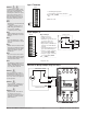
PM PID Controller • 19 • Chapter 2 Install and Wire
Warning: Óç
Use National Electric (NEC) or other
country-specific standard wiring and
safety practices when wiring and
connecting this controller to a power
source and to electrical sensors or
peripheral devices. Failure to do so
may result in damage to equipment
and property, and/or injury or loss
of life.
Note:
Maximum wire size termination and
torque rating:
• 0.0507 to 3.30 mm
2
(30 to 12
AWG) single-wire termination or
two 1.31 mm
2
(16 AWG)
• 0.56 Nm (5.0 lb.-in.) torque
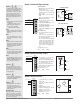
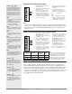
Note:
Adjacent terminals may be labeled
differently, depending on the model
number.
Note:
To prevent damage to the control-
ler, do not connect wires to unused
terminals.
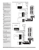
Note:
Maintain electrical isolation between
analog input 1, digital input-outputs,
switched dc/open collector outputs
and process outputs to prevent
ground loops.
Note:
The control output common termi-
nal and the digital common terminal
are referenced to different voltages
and must remain isolated.
Note:
This Equipment is suitable for use in
CLASS I, DIVISION 2, Groups A, B,
C and D or Non-Hazardous locations
only. Temperature Code T4A
Warning:
ç
Explosion Hazard - Dry contact clo-
sure Digital Inputs shall not be used
in Class I Division 2 Hazardous Loca-
tions unless switch used is approved
for this application.
Warning:
ç
Explosion Hazard – Substitution of
component may impair suitability
for
CLASS I, DIVISION 2.
Warning:
ç
Explosion Hazard - Do not discon-
nect while the circuit is live or
unless the area is known to be free
of ignitable concentrations of flam-
mable substances.
0
70
140
210
280
350
420
490
560
630
700
770
840
910
980
1050
1120
1190
1260
1330
1400
1470
1540
1610
1680
1750
1820
1890
1960
2030
2100
2170
2240
2310
2380
2450
2520
2590
2660
2730
2800
2870
2940
3100
3800
4500
5200
5900
6600
7300
8000
0.0
5.0
10.0
15.0
20.0
25.0
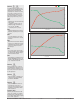
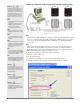
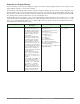
ResistanceinOhms
DO5OutputCurve
Volts mA
0
70
140
210
280
350
420
490
560
630
700
770
840
910
980
1050
1120
1190
1260
1330
1400
1470
1540
1610
1680
1750
1820
1890
1960
2030
2100
2170
2240
2310
2380
2450
2520
2590
2660
2730
2800
2870
2940
3100
3800
4500
5200
5900
6600
7300
8000
0.0
5.0
10.0
15.0
20.0
25.0
ResistanceinOhms
DO6OutputCurve
Volt mA
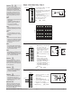
Quencharc Note:
Switching pilot duty inductive loads
(relay coils, solenoids, etc.) with the
mechanical relay, solid state relay or
open collector output options requires
use of an R.C. suppressor.