
User`s manual
Watlow EZ-ZONE
®
PM PID Controller • 9 • Chapter 2 Install and Wire
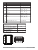
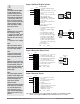
Slot A
Output Terminal Function Configuration
12
X1
W1
Y1
common (Any switched dc output can use this common.)
dc- (open collector)
dc+
Switched dc/open collector
output 1: PM _ _ _ C _-_ AAAA _ _
W2
Y2
dc-
dc+
Switched dc
output 2: PM _ _ _ _ C-_ AAAA _ _
F1
G1
H1
voltage or current -
voltage +
current +
Universal Process
output 1: PM _ _ _ F _-_ AAAA _ _
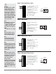
L1
K1
J1
normally open
common
normally closed
Mechanical Relay 5 A, Form C
output 1: PM _ _ _ E _-_ AAAA _ _
L2
K2
normally open
common
No-arc 15 A, Form A (1/16 DIN only)
output 2: PM 6 _ _ _ H-_ AAAA _ _
L2
K2
normally open
common
Mechanical Relay 5 A, Form A
output 2: PM _ _ _ _ J-_ AAAA _ _
L1
K1
L2
K2
normally open
common
Solid-state Relay 0.5 A, Form A
output 1: PM _ _ _ K _-_ AAAA _ _
output 2: PM _ _ _ _ K-_ AAAA _ _
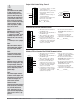
Inputs
1
T1
S1
R1
S2 (RTD) or current +, potentiometer wiper
S3 (RTD), thermocouple -, current - or volts -
S1 (RTD), thermocouple + or volts +
Universal Sensor
input 1: all configurations
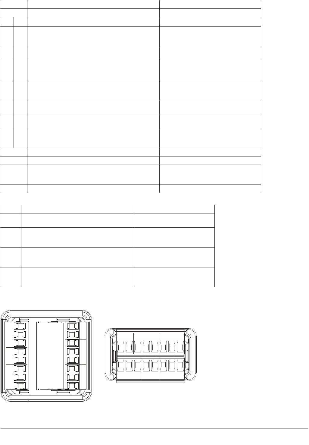
Slot A
Terminal Definitions for Slots A.
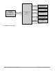
Slot C Terminal Function Configuration
98
99
power input: ac or dc+
power input: ac or dc-
all
CC
CA
CB
Standard Bus or Modbus RTU EIA-485 common
Standard Bus or Modbus RTU EIA-485 T-/R-
Standard Bus or Modbus RTU EIA-485 T+/R+
Standard Bus or Modbus
PM _ _ _ _ _-1 AAAA _ _
CF
CD
CE
Standard Bus EIA-485 common
Standard Bus EIA-485 T-/R-
Standard Bus EIA-485 T+/R+
PM _ _ _ _ _-A AAAA _ _
B5
D6
D5
digital input-output common
digital input or output 6
digital input or output 5
PM _ _ 2 _ _-_ AAAA _ _
PM _ _ 4 _ _-_ AAAA _ _
Terminal Definitions for Slot C.
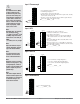
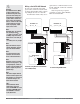
Slot A
Slot B Slot C
Output 1 Output 2 Input 1
Output 3 Output 4 Input 2
Power485 CommsDig I/O 5 & 6
Power
485 Comms
Dig I/O 5 & 6
Slot C
Slot A
Output 1 Output 2 Input 1
C
A