EZ-ZONE RMA (Access) Module User’s Guide ® RMA Module TOTAL CUSTOMER SATISFACTION 3 Year Warranty ISO 9001 Registered Company 1241 Bundy Boulevard., Winona, Minnesota USA 55987 Phone: +1 (507) 454-5300, Fax: +1 (507) 452-4507 http://www.watlow.com 0600-0072-0000 Rev. A November 2010 Winona, Minnesota USA Made in the U.S.A.
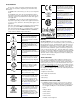
Safety Information Unit is compliant with European Union directives. See Declaration of Conformity for further details on Directives and Standards used for Compliance. We use note, caution and warning symbols throughout this book to draw your attention to important operational and safety information. A “NOTE” marks a short message to alert you to an important detail. Unit has been reviewed and approved by Factory Mutual as a Temperature Limit Device per FM Class 3545 standard. See: www. fmglobal.
• Your P.O. number • Detailed description of the problem • Any special instructions • Name and phone number of person returning the product. 2. Prior approval and an RMA number from the Customer Service Department is required when returning any product for credit, repair or evaluation. Make sure the RMA number is on the outside of the carton and on all paperwork returned. Ship on a Freight Prepaid basis. 3. After we receive your return, we will examine it and try to verify the reason for returning it. 4.
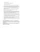
TC Table of Contents Chapter 1: Overview . . . . . . . . . . . . . . . . . . . . . . . . . . . . . . . . . . . . . 3 A Conceptual View of the RM System . . . . . . . . . . . . . . . . . . . . . . . . . . . 4 Chapter 2: Install and Wire. . . . . . . . . . . . . . . . . . . . . . . . . . . . . . . . . 7 Dimensions. . . . . . . . . . . . . . . . . . . . . . . . . . . . . . . . . . . . .
TC Table of Contents (cont.) Chapter 7: RMA Communications . . . . . . . . . . . . . . . . . . . . . . . . . . . 49 EZ-ZONE RMA & Communications. . . . . . . . . . . . . . . . . . . . . . . . . . . . . 49 Modbus . . . . . . . . . . . . . . . . . . . . . . . . . . . . . . . . . . . . . . . . . . . . . . . . . 49 Introduction to the Modbus Protocol . . . . . . . . . . . . . . . . . . . . .
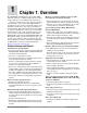
1 Chapter 1: Overview The EZ-ZONE ® Rail Mount Access module (RMA) takes the pain out of adding field bus protocols, data logging and more to your RM system architecture. It just got a whole lot easier to solve the thermal requirements of your system. The RMA module is provided in a space-saving, rail-mount package and is highly scalable where you only pay for what you need. For those applications that require the ability to configure/monitor the control over a network this module will meet the need.
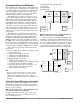
RM Control Slot C RM Expansion Slot C RM Access Slot E The flexibility of the RM’s software and hardware allows a large range of configurations. Acquiring a better understanding of the controllers overall functionality and capabilities while at the same time planning out how the controller can be used will deliver maximum effectiveness in your application.
Module Orientation The picture below reflects a front view of an RMA module. Like all RM modules, there are four slots that appear on the face (slot A, B, D, and E) of the module and one on the bottom (slot C) not shown. For this particular module only slots D and E can be used. On the face of the module there is a button (orange circle) under the Zone address [J] that when pushed and held has the following function: 1.Push and hold for ~ 2 seconds to change the Zone address.
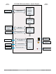
Input Function PLC, PC or OIT EZ-ZONE RM-Access Module - System Diagram EIA - 232/485 or Ethernet Fieldbus Protocol Output Function Protocol of Choice - EtherNet/IP - DeviceNet - Modbus RTU - Modbus TCP - Profibus DP Slot E (optional) Profile Ramp & Soak Battery Backup & Real Time Clock (optional) Storage Device (Configuration, Memory and Data Logging) Micro SD Memory Socket Auto Configuration, Backup, USB Port and Data Logging PC Mini Type B USB Port v1.
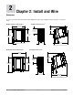
2 Chapter 2: Install and Wire Dimensions As can be seen below the dimensions of the RM system will change slightly based on the type of connector used. Module Removal Clearance Standard Connectors 147.07 mm ( 5.8 in ) 75.08 mm ( 3.0 in ) 44.45 mm ( 1.75 in ) 101.60 mm ( 4.00 in ) 116.08 mm ( 4.57 in ) 150 51.56 mm ( 2.03 in ) Latch in open position 165 mm ( 6.50 in ) Module Removal Displacement Module Removal Clearance Straight Connectors 155 mm ( 6.10 in ) 75.08 mm ( 3.0 in ) 44.45 mm ( 1.
Dimensions Chassis Mount Front View (Module Removed) - Screw Connection Pattern 58.67 mm (2.31 in) 17.53 mm (.69 in) 51.56 mm (2.03 in) 32.77 mm (1.29 in) 60.45 mm (2.38 in) 35.81 mm (1.41 in) 35.05 mm (1.38 in) 16.76 mm (.66 in) The view above is representative of the modular backplane without the module. Recommended chassis mount hardware: 1. #8 screw, 3/4" long 2. Torque to 10 -15 in-lb 3.
Power Supplies DSP60 DSP30 55.6 mm 2.189 in ++ - - L DC OK DSP60 N L N 5 6 6 14.20 mm 0.559 in 14.20 mm 0.559 in 5 Power Supply Specifications DSP100 DSP 30 56.8 mm 2.236 in 89.9 mm 3.539 in 49.00 mm 1.929 in 12 3 4 vout ADJ. 32.10 mm 1.264 in DC LO DC OK 5 6 14.20 mm 0.559 in 5 N 9.75 mm 0.384 in L 43.1 mm 1.
RMA Installation and Removal on a DIN Rail Modular Backplane Connector The picture on the right shows the Modular Backplane Connector, both front and rear view. The rear view is bringing in to focus a metal clip. If the DIN rail is grounded the Modular Backplane Connector and the module connected to it will be also (recommended).
Module Removal To remove a module from the Modular Backplane Connector find the red tab protruding from the bottom of the module and pull back on it as shown to the right. While pulling back on the red tab the two mounting posts will release the module where the module can then be lifted up and out of the Modular Backplane Connector.
Wiring Access Module (RMAx-Axxx-xxxx) Slot A Slot B Slot D Slot E Terminal Function Configuration Modbus RTU - - - - - - - - CB CA CC CB CA C5 C3 C2 - Modbus Modbus Modbus Modbus Modbus Modbus Modbus Modbus RTU RTU RTU RTU RTU RTU RTU RTU Part # Digit 6 Slot A: Not a valid option Slot B: Not a valid option Slot D: Not a valid option Slot E: RMAx-A(2)xx-xxxx EIA-485 T+/R+ EIA-485 T-/REIA-485 common EIA-485 T+/R+ EIA-485 T-/REIA-232 common EIA-232 DB9/pin 2 EIA-232 DB9/pin 3 EtherNet/IP an
All Modules - Front View Standard Connector Slot E Slot D Slot B Slot A 99 98 Slot C power RMA Isolation Block Controller Power Supply 20.4 to 30.8VÎ (dc) 20.4 to 30.
Warning: ç Use National Electric (NEC) or other country-specific standard wiring and safety practices when wiring and connecting this controller to a power source and to electrical sensors or peripheral devices. Failure to do so may result in damage to equipment and property, and/or injury or loss of life. Access Module Wiring (RMAx-xxxx-xxxx) Low Power Slot C 20.4 to 30.
EIA-232/485 Modbus RTU Communications RMA Part # Digit 5 and 6 is A2 Slot E • Wire T-/R- to the A terminal of the EIA-485 port. T-/R• Wire T+/R+ to the B terminal of CA the EIA-485 port. CC common • Wire common to the common T+/R+ CB terminal of the EIA-485 port. CA T-/R• Do not route network wires C5 232 common with power wires. Connect net232 (Tx) to DB9 pin 2 (RD) work wires in daisy-chain fashC3 ion when connecting multiple 232 (RD) to DB9 pin 3 (Tx) C2 devices in a network.
Profibus DP Communications RMA Part # Digit 5 and 6 is A6 Slot E +5Vdc Voltage Potential 485 T+/R+ 485 T-/R- VP B A Digital ground DG Termination resistor B trB 485 T+/R+ 485 T-/RTermination resistor A B A trA • Wire T-/R- to the A terminal of the EIA-485 port. • Wire T+/R+ to the B terminal of the EIA-485 port. • Wire Digital Ground to the common terminal of the EIA-485 port. • Do not route network wires with power wires.
Connecting and Wiring the Modules RM System Connections taining to the split rail system diagram shown below. The power supply used is the 91W supply. The top DIN rail now has the following modules: Components of a RM system can be installed as stand alone modules or can be interconnected on the DIN rail as shown below. When modules are connected together, power and communications are shared between modules over the modular backplane interconnection.
Wiring a Serial EIA-485 Network 120 Ω resistor across T+/R+ and T-/R- of the last controller on a on a network. Do not route network wires with power wires. Connect network wires in daisy-chain fashion when connecting multiple devices in a network. A termination resistor may be required. Place a Note: Termination resistors when used, require a termination resistor at both ends of the network. A network using Watlow's Standard Bus and an RUI/Gateway.
Conventions Used in the Menu Pages the RUI (optional equipment) visual information from the module is displayed to the observer using a fairly standard 7 segment display. Due to the use of this technology, several characters displayed need some interpretation, see the list below: To better understand the menu pages that follow review the naming conventions used. When encountered throughout this document, the word "default" implies as shipped from the factory.
Page under the Backup Menu. For parameters listed as float notice that only one (low order) of the two registers is listed, this is true throughout this document. By default, the low order word contains the two low bytes of the 32-bit parameter. As an example, look in the RMA Setup Page for the Real Time Clock Value. Find the column identified in the header as Modbus and notice that it lists register 1424.
3 Chapter 3: Operations Page Access Module Operation Page Parameters To navigate to the Operations Page using the RUI, follow the steps below: 1. From the Home Page, press both the Up ¿ and Down ¯ keys for three seconds. [``Ai] will appear in the upper display and [oPEr] will appear in the lower display. 2. Press the Up ¿ or Down ¯ key to view available menus. the Up ¿ or Down ¯ key to select and then press the Advance Key ‰ to enter. 5.
Access Module Display Parameter Name Description • Range Operations Page Default Modbus Relative Address Profibus Parameter Data CIP Index ID Type Class & Read/ Instance Write Attribute hex (dec) [dLog] [oPEr] Data Logging Menu [Stat] [Stat] Data Logging [no;M] No Memory (1637) Status [``oH] OK (138) Status indicates the status of the data logging function. OK means logging can be started or can continue. No Memory can indicate the memory card is full or not present.
Access Module Display [2onE] [ZonE] Parameter Name Description • Range Operations Page Default Backup 1 to 16 Zone Current Zone indicates which zone’s configuration is being saved or restored or was last saved or restored.
4 Chapter 4: Setup Pages Access Module Setup Page Parameters To navigate to the Setup Page using the RUI, follow the steps below: 1. From the Home Page, press both the Up ¿ and Down ¯ keys for six seconds. [``Ai] will appear in the upper display and [`Set] will appear in the lower display. 2. Press the Up ¿ or Down ¯ key to view available menus. the Up ¿ or Down ¯ key to select and then press the Advance Key ‰ to enter. 5. Press the Up ¿ or Down ¯ key to move through available menu prompts. 6.
Access Module Parameter name Description Display • Range Setup Page Default Modbus Relative Address CIP Class Instance Attribute hex (dec) Profibus Index Data ParamType eter & Read/ ID Write gLbL] [`Set] Global Menu ---- 0x6A (103) 1 0x1C (28) ---- 3028 uint RWES 26 0x65 (101) 1 0x0E (14) 8 1014 uint RWE 24 0x65 (101) 1 0x0D (13) 7 1013 uint RWE 1 432 0x96 (150) 2 1 76 17007 uint RWE [d;prs] [dPrS] Global Display Pairs Defines the number of Display Pairs.
Access Module Display Parameter name Description • Range Setup Page Default Modbus Relative Address CIP Class Instance Attribute hex (dec) Profibus Index Data ParamType eter & Read/ ID Write [iP;F2] [ip.F2] Communications 0 to 255 IP Fixed Address Part 2 Set the IP address of this module. Each device on the network must have a unique address. 254 ---- ---- ---- 17015 uint RWE [iP;F3] [ip.F3] Communications 0 to 255 IP Fixed Address Part 3 Set the IP address of this module.
Access Module Display Parameter name Description • Range Setup Page Default Modbus Relative Address CIP Class Instance Attribute hex (dec) Profibus Index Data ParamType eter & Read/ ID Write [`Ad;d] [ Ad.d] 0 to 63 Communications DeviceNet™ Node Address Set the DeviceNet™ address for this gateway.
Access Module Display Parameter name Description • Range Setup Page Default Modbus Relative Address CIP Class Instance Attribute hex (dec) Profibus Index Data ParamType eter & Read/ ID Write [M;oF] [M.oF] Local Remote Gateway (1 to 17) Modbus Address Offset When multiple EZ-ZONE controllers are used over Modbus the value entered allows for parameter differentiation from control to the next.
Access Module Display [`s;of] [ S.of] Parameter name Description Gateway (1 to 17) Profibus DP Slot Offset Set Profibus instance member offset for this Standard Bus controller.
Access Module Parameter name Description Display • Range Setup Page Default Modbus Relative Address CIP Class Instance Attribute hex (dec) Profibus Index Data ParamType eter & Read/ ID Write [Mon] [Mon] Real Time Clock Month Set current month for the Real Time Clock. 1 to 12 ---- 1434 0x88 (136) 1 6 38 36006 uint RW [dAtE] [dAtE] Real Time Clock Date Set the current date for the Real Time Clock.
Access Module Display Parameter name Description • Range Setup Page Default Modbus Relative Address CIP Class Instance Attribute hex (dec) Profibus Index Data ParamType eter & Read/ ID Write [dLog] [`SEt] Data Logging Menu [PErd] [PErd] Data Logging Period Use Period to set the time in seconds between when records are entered in the data log. 1 to 3,600 10 1450 0x89 (137) 1 1 49 37001 uint RWES [f;act] [F.
Access Module Display Parameter name Description • Range Setup Page Default Modbus Relative Address CIP Class Instance Attribute hex (dec) Profibus Index Data ParamType eter & Read/ ID Write [Lg;Pt] [`SEt] Log Point Menu [SFn;A] SFn.A] None Log Point (1 to 200) [nonE] None (61) Source Function A [``Ai] Analog Input, (142) Select the source of the point [CUrr] Current (22) to be logged..
Access Module Parameter name Description Display • Range Setup Page Default Modbus Relative Address CIP Class Instance Attribute hex (dec) Profibus Index Data ParamType eter & Read/ ID Write [`Si;A] [Si.A] Log Point (1 to 200) Source Instance A Select the instance of the source identified above.. 1 to 24 1 1472 [offset 16] 0x8B (139) 1 to C8 (200) 2 67 39002 uint RWES [`S2;A] [SZ.A] Log Point (1 to 200) 0 to 16 Source Zone A Select the zone of the source identified above.
Access Module Parameter name Description Display [rESt] [rEst] • Range Setup Page Default Backup [`oFF] Off (62) Restore [noW] Now (1646) Set Restore to Now to re[`Chg] Change (1647) store the configuration of the other zones (modules) to the settings saved in the backup memory. Select Change to have the configuration feature automatically restore settings whenever a module is replaced with a like (same part number but different serial number) module.
5 Chapter 5: Factory Pages Access Module Factory Page Parameters To navigate to the Factory Page using the RUI, follow the steps below: 5. Press the Up ¿ or Down ¯ key to move through available menu prompts. 1. From the Home Page, press and hold both the Advance ‰ and Infinity ˆ keys for six seconds. 6. Press the Infinity Key ˆ to move backwards through the levels: parameter to submenu; submenu to menu; menu to Home Page. 2. Press the Up ¿ or Down ¯ key to view available menus. 7.
Access Module Display Parameter Name Description Range • Factory Page Default CIP Modbus Relative Address Class Instance Attribute hex (dec) Profibus Parameter Index ID Data Type & Read/ Write [`LoC] [FCty] Security Setting Menu [LoC;o] [LoC.o] Security Setting Operations Page Change the security level of the Operations Page. 1 to 3 2 362 0x67 (103) 1 2 ---- 3002 uint RWE [pas;e] [PAS.
Access Module Display [pas;a] [PAS.A] Parameter Name Description Security Setting Administrator Password Set administrator password Used to acquire full access to change passwords.
Access Module Display Parameter Name Description Range • Factory Page CIP Modbus Relative Address Class Instance Attribute hex (dec) DHCP ---- ---- ---- 17013 uint RW Default Profibus Parameter Index ID Data Type & Read/ Write [iP;AC] [iP.AC] Diagnostics Menu Actual IP Addressing Mode [none] None (61) [dhCP] DHCP (1281) [F;Add] Fixed Address (1284) [fail] Fail (32) [iP;A1] [iP.A1] Diagnostics Menu IP Actual Address Part 1 0 to 255 ---- ---- ---- ---- 17044 uint RW [iP;A2] [iP.
6 Chapter 6: RMA Features Dimensions . . . . . . . . . . . . . . . . . . . . . . . . . . . . . . . . . . . . . . . . . . . 7 Access Module Factory Page Parameters. . . . . . . . . . . . . . . . . . . . . . 35 Saving And Restoring User Settings . . . . . . . . . . . . . . . . . . . . . . . . . 40 Using Lockout to Hide Pages and Menus . . . . . . . . . . . . . . . . . . . . . . 40 Using Password Security .
Saving And Restoring User Settings Recording setup and operations parameter settings for future reference is very important. If you unintentionally change these, you will need to program the correct settings back into the controller to return the equipment to operational condition. After you program the controller and verify proper operation, use User Save Set [USr;S] (Setup Page, Global Menu) to save the settings into either of two files in a special section of memory.
with a password would have visibility restricted by the Read Lockout Security [rloC] . As an example, with Password Enabled and the Locked Access Level [loC;L] set to 1 and [rloC] is set to 3, the available Pages for a user without a password would be limited to the Home and Factory Pages (locked level 1). If the user password is entered all pages would be accessible with the exception of the Setup Page as defined by level 3 access. How to Enable Password Security 1.
RTC is required to use this feature. As an example, if the Power Off Time were set to 300 and the power is lost while a profile is executing and then restored before 5 minutes expires, the profile would continue where it was at prior to the loss of power. If the power were to be restored after 300 seconds expires the profile would be terminated. Data Logging The RMA module equipped (RMAX-XXXD-XXXX) and configured for data logging is capable of recording data points every second to every hour.
Software Configuration Using EZ-ZONE® Configurator Software To enable a user to configure the RMA module using a personal computer (PC), Watlow has provided free software for your use (Windows® XP only). If you have not yet obtained a copy of this software insert the CD (Controller Support Tools, delivered with the module) into your CD drive and install the software.
In the previous screen shot the RMA is shown highlighted to bring greater clarity to the module in focus. Any EZ-ZONE device on the network will appear in this window and would be available for the purpose of configuration or monitoring. After clicking on the module of choice simply click the next button once again. The next screen appears below. erations Menu will appear next and perhaps deliver more clarity for the area of focus by not displaying unwanted menus and parameters.
Lastly, when the configuration is complete click the "Finish" button at the bottom right of the previous screen shot. The screen that follows this action can be seen below. Although the RMA module now contains the configuration (because the previous discussion focused on doing the configuration on-line) it is suggested that after the configuration process is completed that the user save this file on the PC for future use.
Function Block Descriptions [dLog] Data Logging Menu [`SEt] Setup Page Each of the next several pages graphically shows each of the RMA function blocks. Note that as you view each you will find text that is black and text that appears gray. The gray text represents inputs that are not currently available based on the functions defined use (red text).
Diagnostics Function Real Time Clock Function Device Name : EZ-ZONE RM The RTC allows profiles to pause until a given amount time elapses or a given date occurs. It also allows for a date and time stamp when data logging.
Variable Function Ranges specified in units or degrees F if expressed in degrees C, range is smaller Error: None, Open, Shorted, Measurement Error, Bad Cal Data, Ambient Error, RTD Error, Fail, Math Error, Not Sourced, Stale Function passes stored value to output. [``o; u ] Output value: -1,999000 to 9,999.
7 Chapter 7: RMA Communications EZ-ZONE RMA & Communications With the introduction of the first Programmable Logic Controllers (PLC's) in the early to mid 1970's it quickly became apparent that there was a need to communicate between one PLC and another, and then on a wider scale, between PLC's and other computers within the company infrastructure.
parameter, therefore, within the user program when writing a new value to Modbus registers 200 and 201 the RMC loop 1 Closed Loop Set Point will change accordingly. So, when the Modbus address of a target parameter is stored in an "Assembly Definition Address" its corresponding working address will return that parameter’s actual value. If it’s a writable paModbus Offset 0 and the lower display shows [bAUd]. Use the up and or down arrow key to change the baud rate. 6.
the front panel for six seconds to go the the Setup Menu. 2. Push the up or down arrow key until [gtw] (Gateway Menu) appears in the upper display and [`SEt] in the lower display. 3. Push the green Advance Key ‰ to begin configuration of the first gateway instance (RM module zone 1). The upper display shows instance one [1] and the lower display shows the gateway prompt [gtw]. 4.
perature units. The upper display shows [```f] and lower display shows [`C_f]. Use the up or down arrow key to change the temperature units. 9. Push the Advance Key ‰ to change the Nonvolatile Save setting. The upper display shows [`yes] and lower display shows [`nU;s]. Use the up or down arrow key to change the Nonvolatile Save setting. 10. Push the Infinity Key ˆ three times or push and hold for approximately 3 seconds to navigate back to the Home Page.
Note: bit assembly member there is also a Compact Class of the assembly. The need for the Compact Class of assembly members became apparent as the high density RM modules (up to 16 control loops) were being developed. The Compact Class allows for better utilization of each bit within an assembly member by compacting parameters within one 32-bit assembly member.
Note: Application Note: Assume that in the following graphic there are 4 RMC modules on the network with each having 4 instances of an Analog Input. If it is desired to access all of the Analog Inputs from each module the CIP offset must, at a minimum, have an offset of 4 between each module (gateway instance). If the offset for each module is set as shown on the following page, the 4th instance would not be available.
Link Status Indicator Steady Off Red Green Not powered, unknown link speed If the device cannot determine link speed or power is off, the network status indicator shall be steady off. the device is communiLink speed = If cating at 10 Mbit, the link 10 Mbit LED will be red.. the device is commuLink speed = If nicating at 100 Mbit, the 100 Mbit link LED will be green. Activity Status Indicator Flashing Green Detects activity If the MAC detects activity, the LED will be flashing green.
Setting DeviceNet Communication Parameters from the RUI Front Panel Module Status (MOD) Indicator LED Description Valid DeviceNet node addresses range from 0 - 63 and there are three available baud rates (network speed) for the user to choose from: 125Kb, 250Kb, or 500Kb. The EZ-ZONE RMA factory defaults are listed below: Off No power is applied to the device. Flashing GreenRed The device is performing a self-test. Flashing Red Major Recoverable Fault. Red Major Unrecoverable Fault.
8. Push the up or down arrow key to enable or disable the quick connect feature. 9. Push the green Advance key ‰ once to change the temperature units passed over DeviceNet where the lower display shows [`C_F] and the top display will show [```f] or [```C] based on the current setting. 10. Push the up or down arrow to change to the temperature units. 11. Push the Infinity Key ˆ three times or push and hold for approximately 3 seconds to navigate back to the Home Page.
Profibus DP RMA LED Indicators via EZ-ZONE Configurator software. This parameter can be found in the User's Guide for each RM module in the Setup Page under the Communications Menu. Viewing the unit from the front and then looking on top of the RMA two bicolor LED's can be seen where only the front one is used. Definition follows: Closest to the Front Indicator LED Red Red Flashing Green Note: This setting must be changed to the desired setting for each module individually.
Chapter 8: Appendix Modbus - User Programmable Memory Blocks Assembly Definition Address and Assembly Working Addresses Definition Addresses Working Addresses Definition Addresses Working Addresses 40 & 41 200 & 201 120 & 121 280 & 281 42 & 43 202 & 203 122 & 123 282 & 283 44 & 45 204 & 205 124 & 125 284 & 285 46 & 47 206 & 207 126 & 127 286 & 287 48 & 49 208 & 209 128 & 129 288 & 289 50 & 51 210 & 211 130 & 131 290 & 291 52 & 53 212 & 213 132 & 133 292 & 293 54 & 55 214 & 21
Modbus Default Assembly Structure 40-119 Assembly Definition Addresses Default Pointers Assembly Working Addresses Registers 40 & 41 Registers 200 & 201 Pointer 1 = 0 & 1 Closed Loop Set Point 1 Registers 42 & 43 Pointer 2 = 0 & 1 Closed Loop Set Point 2 Registers 44 & 45 Pointer 3 = 0 & 1 Closed Loop Set Point 3 Registers 46 & 47 Pointer 4 = 0 & 1 Closed Loop Set Point 4 Registers 48 & 49 Pointer 5 = 0 & 1 Open Loop Set Point 1 Registers 50 & 51 Pointer 6 = 0 & 1 Open Loop Set Point 2 Registers 52
Modbus Default Assembly Structure 120-199 Assembly Definition Registers Default Pointers Assembly Working Registers Assembly Definition Registers Default Pointers Assembly Working Registers Registers 120 & 121 Registers 280 & 281 Registers 160 & 161 Registers 320 & 321 Pointer 41 = 0 & 1 Undefined Registers 122 & 123 Pointer 42 = 0 & 1 Undefined Registers 124 & 125 Pointer 43 = 0 & 1 Undefined Registers 126 & 127 Pointer 44 = 0 & 1 Undefined Registers 128 & 129 Pointer 45 = 0 & 1 Undefined
CIP Implicit Assembly Structure RMA / RME CIP Implicit Assembly Defaults CIP Implicit Assembly Originator (Master) to Target (RMA / RME) Assembly Members Assembly Class, Instance, Attritbute RM Module Data Type Parameter Parameter Class, Instance, Attritbute PLC Data Type 1 0x77, 0x01, 0x01 DINT None specified 0x0, 0x00, 0x00 undefined 2 0x77, 0x01, 0x02 DINT None specified 0x0, 0x00, 0x00 undefined 3 0x77, 0x01, 0x03 DINT None specified 0x0, 0x00, 0x00 undefined 4 0x77, 0x01, 0x04
RMH / RMS / RML CIP Implicit O to T Assembly Defaults CIP Implicit Assembly Originator (Master) to Target (RMH / RMS / RML) Assembly Members Assembly Class, Instance, Attritbute RM Module Data Type Parameter Parameter Class, Instance, Attritbute PLC Data Type 1 0x77, 0x01, 0x01 DINT None specified 0x01, 0x01, 0x00 undefined 2 0x77, 0x01, 0x02 DINT None specified 0x0, 0x00, 0x00 undefined 3 0x77, 0x01, 0x03 DINT None specified 0x0, 0x00, 0x00 undefined 4 0x77, 0x01, 0x04 DINT None
RMH / RMS / RML CIP Implicit T to O Assembly Defaults CIP Implicit Assembly Target (RMH / RMS / RML) to Originator (Master) Assembly Members Assembly Class, Instance, Attritbute RM Module Data Type Parameter Parameter Class, Instance, Attritbute PLC Data Type 1 Cannot be changed Binary Device Status none DINT 2 0x77, 0x02, 0x01 DINT None specified 0x0, 0x00, 0x00 undefined 3 0x77, 0x02, 0x02 DINT None specified 0x0, 0x00, 0x00 undefined 4 0x77, 0x02, 0x03 DINT None specified 0x0,
RMC CIP Implicit Assembly Defaults CIP Implicit Assembly Originator (Master) to Target (RMC) Assembly Members Assembly Class, Instance, Attritbute RM Module Data Type Parameter Parameter Class, Instance, Attritbute PLC Data Type 1 0x77, 0x01, 0x01 DINT Control Loop 1, Closed Loop Set Point 0x6B, 0x01, 0x01 REAL 2 0x77, 0x01, 0x02 DINT Control Loop 2, Closed Loop Set Point 0x6B, 0x02, 0x01 REAL 3 0x77, 0x01, 0x03 DINT Control Loop 3, Closed Loop Set Point 0x6B, 0x03, 0x01 REAL 4 0x77
As can be seen on the previous page the RMC module is the only RM module that defaults to a populated assembly structure. If it is desired to use the implicit assembly for any of the other RM modules the assembly structure must be built by the user. Their are many software tools available to modify the assembly structure and it is outside of the scope of this document to describe how to use those. What can be found in this document is the process to build the assembly structure.
Compact Class MSW A Assembly Class, Instance, Attribute (C) 0x71 (113) Control Loop (I) 1 to 24 T2O (A) 1 Module Availabilty 31 30 29 28 27 26 25 24 23 22 21 20 19 18 17 16 19 18 17 16 19 18 17 16 Filtered Analog Input Value (instance i) RMH Bits 16 to 31, Signed 16 bits with implied tenths precision (-3276.8 to 3276.
Compact Class LSW A 15 14 Input error status Loop error status 13 12 Actual CM 11 10 9 8 7 Tune status 6 5 4 3 2 1 0 3 2 1 0 3 2 1 0 Control Loop Output Power (instance i) Bits 0 to 10, Signed 10 bits with implied tenths precision (-100.0 to 100.
Compact Class MSW B Assembly Class, Instance, Attribute Control Loop (C) 0x71 (113) (I) 1 to 24 O2T (A) 3 Assembly Class, Instance, Attribute Control Loop (C) 0x71 (113) (I) 1 to 24 O2T (A) 4 Assembly Class, Instance, Attribute Control Loop (C) 0x71 (113) (I) 1 to 24 O2T (A) 5 Assembly Class, Instance, Attribute Limt Loop O2T (C) 0x71 (113) (I) 1 to 24 (A) 0x0A (10) Module Availabilty 31 30 29 28 27 24 23 22 21 20 19 18 17 16 19 18 17 16 20 19 18 17 16 20 19 18 17 16
Compact Class LSW B 15 14 13 12 11 10 9 8 7 6 5 4 3 2 1 0 5 4 3 2 1 0 5 4 3 2 1 0 5 4 3 2 1 0 4 3 2 1 0 Closed Loop Set Point (instance i) Bits 0 to 15, Signed 16 bits with implied tenths precision (-3276.8 to 3276.7) 15 14 13 12 11 10 9 8 7 6 Integral Time (instance i) Bits 0 to 15, Unsigned 16 bits whole (0 to 6553.5) 15 14 13 12 11 10 9 8 7 6 Derivative Time (instance i) Bits 0 to 15, Unsigned 16 bits whole (0 to 6553.
RMA Specifications grammable function key • Typical display update rate 1Hz Line Voltage/Power • 20.4 to 30.8Vı (ac/dc), 50/60Hz, ±5 percent • Any external power supply used should comply with a class 2 or SELV rating.
EZ-ZONE Rail-Mount Access Module Ordering Information Access module requires a Class 2 or SELV power supply 20.4 to 30.8 V ~(ac) / port for configuration with EZ-ZONE Configurator software. (dc), communication Code Number 1 2 3 EZ-ZONE Rail Mount Access Module RM A 9 10 8 Sys. Conf.
Index [`Ad;d] DeviceNet Address 27 [Ad;M] Modbus Address 25 [Ai;nb] Implicit Input Assembly Quantity 28 [a;loc] Profibus Address Lock 27 [AME] Available Memory 22 [anLg] Analog Variable 34 [Ao;nb] Implicit Output Assembly Quantity 28 [`A;ti] Available Logging Time 22 [`A;ti] Available Logging Time 22 [bAUd] Baud Rate 25 [bAUd] Baud Rate 25 [bCUP] Backup Menu 22, 23, 33 [`C_F] Display Units 27 [Code] Public Key 37 [CoM] Communications Menu 25, 32 [dAtE] Date 30 [dAtE] Date of Manufacture 37 [`dEC] Display P
M U Modbus User Programmable Memory Blocks 49 Assembly Definition Addresses 49 Assembly Working Addresses 49 Using Modbus RTU 50 Using Modbus TCP 52 O User Password 36 User Programmable Memory Blocks 49 User Restore Set 25, 40 User Save Set 25, 40 Using DeviceNet™ 55 Using EtherNet/IP™ 53 Using EZ-ZONE® Configurator Software 43 Using Modbus RTU 50 Using Modbus TCP 52 operator interface 71 V P Variable Menu 34 Parity 25 Password 35, 37 Power Off Time 41 power supplies 9 Profibus DP 57 Introduction t
Declaration of Conformity EZ Zone Series RM WATLOW an ISO 1241 Bundy Blvd. Winona, MN 55987 USA 9001 approved facility since 1996. Declares that the following Series RM (Rail Mount) products: Model Numbers: RM followed by additional letters or numbers describing use of up to four module options of various inputs and outputs or communications.
How to Reach Us Corporate Headquarters Watlow Electric Manufacturing Company 12001 Lackland Road St. Louis, MO 63146 Sales: 1-800-WATLOW2 Manufacturing Support: 1-800-4WATLOW Email: info@watlow.com Website: www.watlow.com From outside the USA and Canada: Tel: +1 (314) 878-4600 Fax: +1 (314) 878-6814 Latin America Watlow de México S.A. de C.V. Av. Fundición No. 5 Col. Parques Industriales Querétaro, Qro. CP-76130 Mexico Tel: +52 442 217-6235 Fax: +52 442 217-6403 Europe Watlow France Tour d'Asnières.