
User`s guide


Watlow EZ-ZONE
®
RM A M odule • 50 • Chapter 7 RMA Communi ca tions
parameter, therefore, within the user program when
writing a new value to Modbus registers 200 and 201
the RMC loop 1 Closed Loop Set Point will change
accordingly. So, when the Modbus address of a target
parameter is stored in an "Assembly Definition Ad-
dress" its corresponding working address will return
that parameter’s actual value. If it’s a writable pa-
rameter, as in the case described above, writing to its
working registers will change the parameters actual
value.
Using Modbus RTU
Configuring the Gateway
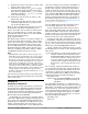
If using and RUI, reference the graphic below as an
example, and follow the steps provided to configure
the Modbus communication port as well as each gate-
way instance (RM Module).
Communications Port Settings:
Starting from the RUI Home Page.
1. Push and hold the up and down arrow keys
on the front panel for six seconds to go the the
Setup Menu.
2. Push the up or down arrow key until [CoM]
(Communications Menu) appears in the upper
display and [`SEt] in the lower display.
3. Push the green Advance Key
‰
to enter the
Communications Menu. The upper display
shows the current Modbus address ( [1], factory
default) and the lower display shows the ad-
dress prompt [ad;m].
4. Push the up arrow key until the chosen ad-
dress appears in the upper display.
5. Push the green Advance Key
‰
to change the
baud rate. The upper display shows [9600],
and the lower display shows [bAUd]. Use the
up and or down arrow key to change the baud
rate.
6. Push the Advance Key
‰
to view the current
parity setting. The upper display shows [nonE]
and lower display shows [PAr]. If desired, use
the up and or down arrow key to change the
parity.
7. Push the Advance Key
‰
to view the Modbus
TCP Word Order, which allows the user to
swap the high and low order 16-bit values of a
32 bit member.. The factory default is [lohi]
low/high as shown in the upper display and
the lower display shows the byte order prompt
[m ;hl] .
8. Push the Advance Key
‰
to view the current
units as passed between gateway devices and
the master on the network. The upper display
shows [```f] and lower display shows [`C_f].
If desired, use the up and or down arrow key to
change the units.
9. Lastly, push the Advance Key
‰
to view wheth-
er or not parameters written from the master
device (typically a PLC) will be saved in the
slave (RM module). The upper display shows
[`yes] or [``no] and lower display shows the
non-volatile save prompt [`nU;s]. If desired, use
the up and or down arrow key to change the
from yes to no.
10. Push the Infinity Key ˆ three times or push
and hold for approximately 3 seconds to navi-
gate back to the Home Page.
Gateway Settings:
Starting from the RUI Home Page.
1. Push and hold the up and down arrow keys on
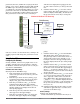
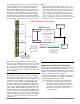
RMA with Modbus RTU Gateway
OIT, PC, PLC
Modbus RTU
RMA/Gateway
RMA/Gateway ( [gtW] ) Setup
Gateway Prompts
[gtW] 1 = RM 1
[gtW] 4 = RM 4
Modbus Offset
0
Modbus Offset
30000
Modbus Offset
20000
Modbus Offset
10000
Baud Rate
[baud] = 9.6, 19.2, 38.4kb
[Com]
Modbus Address
[Ad;m] = 1-247
Parity
[par] = [none], [euen], [odd]
Modbus Word Order
[M;hl] = [lohi] or [hilo]
[gtW] = 1 - 17
(Gateway Instance)
[Du;En] = Yes or No
(Enable gateway instance)
[Du;st] = [On] or [off]
(Device Status)
[MoF] = 0 - 9999
(Modbus Offset)
Watlow Standard Bus
(Daisy chain EIA-485)
EZ-ZONE Controllers
1 - 17 maximum