
User`s guide


Watlow EZ-ZONE
®
RM A M odule • 53 • Chapter 7 RMA Communi ca tions
bit assembly member there is also a Compact Class
of the assembly. The need for the Compact Class of
assembly members became apparent as the high
density RM modules (up to 16 control loops) were be-
ing developed. The Compact Class allows for better
utilization of each bit within an assembly member
by compacting parameters within one 32-bit assem-
bly member. As an example, if a standard assembly
member were configured as a Variable just 7 bits out
of the 32 will be used to write an off (62) or on (63)
status to the module. With the Variable Compact
Class in use, 16 Variables can be placed in one 32-bit
assembly member using just 2 bits for each (00 = off,
01 = on). There is a variety of predefined Compact
Class members that can be used (See Appendix: CIP
Compact Class Assemblies) to modify the default im-
plicit assemblies.
Modifying Implicit Assembly Members
To change any given member of either assembly (T
to O or O to T) simply write the new class, instance
and attribute to the member location of choice. As an
example, if it were desired to change the 14
th
mem-
ber of the O to T assembly of an EZ-ZONE RMH
module from the default parameter (none specified)
to Digital Output State (see RMH User's Guide, Op-
erations Page, Digital Input/Output Menu) write the
value of 0x6A, 0x01 and 0x07 (Class, Instance and
Attribute respectively) to 0x77, 0x01 and 0x0E. Once
the change is executed, reading this member location
will return either an on (63) or off (62) state. This op-
eration to modify the assembly would be the same if
using one of the given Compact Class members dis-
cussed above.
Note:
When changing the implicit assembly of any given
RM module through the RMA, ensure that the CIP In-
stance Offset is added to the documented instance for
any given parameter as well as the assembly instance.
As an example, if it were desired to do the above op-
eration on RM 3 in the DeviceNet graphic the value
to write would now be 0x6A, 0x09 and 0x01 (Class,
Instance and Attribute respectively) to 0x77, 0x09 and
0x0E. Notice that the CIP Offset was added to each.
Using EtherNet/IP™
Communications To/From Third Party Device:
When using the EtherNet/IP protocol, there are two
methods used in communicating, implicitly (See: CIP
Implicit Assemblies) and explicitly. Once the gateway
instance is enabled there are two prompts that relate
directly to these forms of communication.
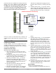
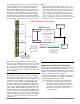
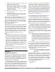
Reference the graphic above (RMA with Ethernet
Gateway) along with the green prompts when read-
ing the descriptions that follow below.
[`ost] CIP Offset, used exclusively with explicit
messages where this prompt defines the
parameter instance as well as the module
on the network. The CIP offset is unique
to each gateway instance (RM module) and
should not overlap from one gateway in-
stance to another.
RMA with Ethernet Gateway
RMA/Gateway
[gtW] 1 = RM 1
[gtW] 4 = RM 4
EtherNet Addressing Mode
[ip;m] = [dhCp] or [F;Add]
[Com]
Modbus Word Order
[M;hl] = [lohi] or [hilo]
Modbus TCP Enable
[Mb;e] = Yes or No
EtherNet/IP Enable
[Eip;e] = Yes or No
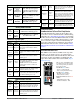
EtherNet/IP
PLC
OIT, PC, PLC
Modbus TCP
Modbus Offset
30000
CIP Offset
13- 255
Modbus Offset
20000
CIP Offset
9- 11
Modbus Offset
10000
CIP Offset
5 - 8
Modbus Offset
0
CIP Offset
1- 3
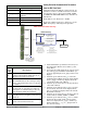
RMA/Gateway ( [gtW] ) Setup
Gateway Prompts
[gtW] = 1 - 17
(Gateway Instance)
[Du;En] = Yes or No
(Enable gateway instance)
[Du;st] = [On] or [off]
(Device Status)
[MoF] = 0 - 9999
(Modbus Offset)
Modbus TCP
[oSt] = 0 - 255
(Offset)
[Ai;nb] = 0 - 40
(Consumed Assembly Size)
EtherNet/IP (CIP Network)
[Ao;nb] = 0 - 40
(Produced Assembly Size)
Watlow Standard Bus
(Daisy chain EIA-485)
EZ-ZONE Controllers
1 - 17 maximum