EZ-ZONE™ PM Controller Communications Manual TOTAL CUST CUS TOMER SATISF TISFA ACTI CTIO ON 3 Year Warranty ISO 9001 Registered Company Winona, Minnesota USA 1241 Bundy Boulevard., Winona, Minnesota USA 55987 Phone: +1 (507) 454-5300, Fax: +1 (507) 452-4507 http://www.watlow.com 0600-0056-0000 Rev. B November 2007 Made in the U.S.A. $15.
Safety Information • Complete model number We use note, caution and warning symbols throughout this book to draw your attention to important operational and safety information. • All configuration information A “NOTE” marks a short message to alert you to an important detail. A “CAUTION” safety alert appears with information that is important for protecting your equipment and performance. Be especially careful to read and follow all cautions that apply to your application.
Table of Contents Chapter 1 PM Communications . . . . . . . . . . . . . . . . . . . . . . . . . . . . . .3 EZ-ZONE™ PM & Communications . . . . . . . . . . . . . . . . . . . . . . . . . . . . 3 Protocols . . . . . . . . . . . . . . . . . . . . . . . . . . . . . . . . . . . . . . . . . . . . . . . . 3 Chapter 2 Modbus RTU & TCP. . . . . . . . . . . . . . . . . . . . . . . . . . . . . . .4 Modbus Remote Terminal Unit (RTU) and Modbus TCP . . . . . . . . . . . .
Watlow EZ-ZONE™ Modbus Communications • 2 • Table of Contents
1 Chapter 1 PM Communications EZ-ZONE™ PM & Communications With the introduction of the first Programmable Logic Controllers (PLCs) in the early to mid 1970s it quickly became apparent that there was a need to communicate between one PLC and another, and then on a wider scale, between PLCs and other computers within the company infrastructure.
2 Chapter 2 Modbus RTU & TCP Modbus Remote Terminal Unit (RTU) and Modbus TCP Gould Modicon, now called AEG Schneider, created the protocol refered to as "Modbus" used in process control systems. Modbus provides the advantage of being extremely reliable in exchanging information, a highly desirable feature for industrial data communications. This protocol works on the principle of packet exchanges.
If your model number has a two in the identified placeholder (PM_ _ _ _ _- [2] _ _ _ _ _ _) then these defaults apply. Port 1 = Standard Bus Port 2 Address ([Ad;S]) = 1 Protocol ([PCoL]) = Modbus Address ([Ad;M]) = 1 Baud Rate ( [bAUd]) = 9600 Parity ([PAr]) = none When two ports are available as the above part number indicates, port one will always be Standard bus with no option to change.
Table 2.
Figure 2.2 & 2.
5. Push the green Advance Key ‰ to change the baud rate. The upper display shows [9600], and the lower display shows [bAUd]. Use the up and or down arrow key to change the baud rate. 6. Push the Advance Key ‰ to change parity. The upper display shows [nonE] and lower display shows [PAr]. Use the up and or down arrow key to change the parity. Figure 2.4 and 2.5 below capture the settings for channel 0 from the PLC used for this example. Figure 2.4 Figure 2.
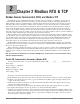
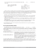
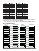
Figure 2.6 As stated previously, the assembly structure is a group of 40 pairs of addresses. The value in each of these addresses serves as a pointer to a parameter within the PM. Each of the 40 pairs of assembly definition addresses are displayed in figures 2.0 - 2.3. In figure 2.7 below, N11:100 through N11:179 shows the factory default values after the MSG instruction is enabled and executed without error.
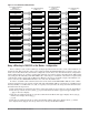
In the example logic below a message instruction is configured to write a new parameter to the first member of the Assembly Definition Addresses. Figure 2.8 Because each of the assembly definition addresses and working registers are 32-bits it is necessary to set this instruction to write to multiple registers, in this case 2. Within figure 2.8 we see an inset image that reflects what is being written to the PM (N11:12 = 1328 and N11:13 = 0).
Lastly, the logic example below will read the process value (40361 and 40360) in from the PM and place it in N11:0 and N11:1. The copy word instruction that follows will then simply deposit what's in N11:0 and N11:1 into floating point address F8:0 (inset graphic in figure 2.11) where we see the current temperature is ~275 o Figure 2.10 Figure 2.
Reading & Writing 32-Bit PM Parameters The process value of the EZ-ZONE™ PM is contained in two 16-bit registers. Register 360 contains the two lower bytes (least significant word, LSW) while register 361 contains the two higher bytes (most significant word, MSW). The 32-bit answer is an IEEE 754, 32-bit float data type. As an example: 977D 429C is in Low Word – High Word Order. Changing to High Word – Low Word, the value is 429C 977D. 429C977D = 78.
o Table 2.2 Binary Received from the Read Analog Input 1 Process Value 78.
Received from Writing Closed Loop Set Point of 75.0 oF Table 2.
Communications Using Modbus TCP Over Ethernet Ethernet Indicator Lights The PM has four indicator lights on the top of the controller, two of which are not used for Modbus TCP. The Module Status and Network Status LED’s apply only when EtherNet/IP is enabled. The characteristics of the Activity and Link indicator lights are defined in the Ethernet specification. Link Status Indicator Table 2.
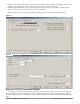
Configuring Modbus TCP Communications with KepserverEX The following screenshots show a sequential step-by-step process to sucessfully establish communications from the PM controller equipped with Modbus TCP and KepserverEX.
Watlow EZ-ZONE™ Communications • 17 • Chapter 2 Mobbus RTU & TCP
Watlow EZ-ZONE™ Communications • 18 • Chapter 2 Mobbus RTU & TCP
Watlow EZ-ZONE™ Communications • 19 • Chapter 2 Mobbus RTU & TCP
Watlow EZ-ZONE™ Communications • 20 • Chapter 2 Mobbus RTU & TCP
Watlow EZ-ZONE™ Communications • 21 • Chapter 2 Mobbus RTU & TCP
Watlow EZ-ZONE™ Communications • 22 • Chapter 2 Mobbus RTU & TCP
Watlow EZ-ZONE™ Communications • 23 • Chapter 2 Mobbus RTU & TCP
Watlow EZ-ZONE™ Communications • 24 • Chapter 2 Mobbus RTU & TCP
Watlow EZ-ZONE™ Communications • 25 • Chapter 2 Mobbus RTU & TCP
Watlow EZ-ZONE™ Communications • 26 • Chapter 2 Mobbus RTU & TCP
Watlow EZ-ZONE™ Communications • 27 • Chapter 2 Mobbus RTU & TCP
Watlow EZ-ZONE™ Communications • 28 • Chapter 2 Mobbus RTU & TCP
3 Chapter 3 EtherNet/IP Introduction to EtherNet/IP Today, with the introduction of EtherNet/IP (Industrial Protocol), a user can collect, configure, and control using one protocol. EtherNet/IP is a network communication standard capable of handling large amounts of data at speeds of 10 Mbps or 100 Mbps, and at up to 1,500 bytes per packet. The specification uses an open protocol at the application layer.
EtherNet/IP Indicator Lights The PM has four indicator lights on the top of the controller, all of which are used with EtherNet/IP. The characteristics of the Module Status and Network Status LED’s are defined by Open DeviceNet Vendors Association (ODVA), while the Active and Link indicator lights are defined in the Ethernet specification. Module Status Indicator Table 3.
I/O Configuration using an Allen-Bradley Logix Family Processor The setup steps may vary depending on the controller. The specific control used in the examples is a CompactLogix 1769-L32E. Follow the steps below to add and configure the PM as a generic Ethernet module. 1. In the I/O configuration, right click on the Ethernet Port, (in this case: 1769-L32E Ethernet Port LocalENB) and add a new module. Figure 3.0 2. Select “Generic Ethernet Module” and click OK.
Name This field, will automatically be used as the controller name and will be used in the program when referencing PM inputs or outputs. Description No entry required. Comm Format As can be seen in the PM I/O assemblies below, the PM data formats depend on the tag name being written to or read from. As can be seen in the chart below, the data types used by the PM vary. Although multiple “Comm Formats” can be configured, for ease in configuration and programming it is suggested that it be configured as INT.
Table 3.5 Supported Attribute Data Types CIP PM Access Size (Bytes) USINT UByte RW 1 SINT Byte RW 1 UINT UWord RW 2 INT Word RW 2 UDINT ULong RW 4 DINT Long RW 4 REAL Float RW 4 Target to Originator (T to O) - Default Assembly Table 3.
Originator to Target (O to T) - Default Assembly Table 3.
Communications between ControlLogix & the EZ-ZONE™ PM Configuring the PM enables both real-time I/O connections (implicit messaging) and non-time critical (explicit messaging) communications. Information will be transferred between the control and the PM using either implicit and or explicit connections. All implicit messages are sent and received cyclically at the rate of the Requested Packet Interval (RPI), where explicit messages are typically initiated via a message instruction in the control program.
Figure 3.5 & 3.6 You can now use simple logic to create instructions to move implicitly the default assembly structures to and from the PM. Recall that the name given to the I/O module is also used as the I/O tags. Note in the first copy instruction (input from PM to PLC) that the name given to the module appears as the source (Watlow_PM). Likewise, in the second copy instruction (output from PLC to PM) the destination tag reflects the module name.
Originator to Target (PLC to PM) Table 3.
For example, the screen captures below explain and illustrate how to change a given member for both the O-to-T and T-to-O assemblies. To change other members within either instance, simply change the instance (1 or 2) and attribute value (1 to 20) in the MSG instruction. For a better understanding of what happens when the instruction is enabled, take a closer look at the message instruction configuration and its associated tags. Figure 3.
Saving Settings to Non-volatile Memory When controller settings are entered from the controller front panel or a remote user interface (RUI) changes are always saved to non-volatile memory (EEPROM). If the controller loses power or is switched off its settings will be restored when power is reapplied. The EEPROM will wear out after about 1,000,000 writes, which should not be a problem with changes made from the panel or RUI.
4 Chapter 4 DeviceNet Introduction to DeviceNet DeviceNet is a low-cost communication link that connects industrial devices over a common network (such as: Watlow temperature controllers, limit switches, photoelectric sensors, proximity sensors, valve manifolds, motor starters, process sensors, bar code readers, variable frequency drives, panel displays, and operator interfaces) to higher-level devices such as programmable controllers and computers.
Setting DeviceNet Communication Parameters from the Front Panel Valid DeviceNet node addresses range from 0 - 63 and there are three available baud rates for the user to choose from: 125Kb, 250Kb, or 500Kb. The EZ-ZONE™ PM factory defaults are listed below: Node address = 63, Baud rate = 125Kb If the node address needs to be changed go to the control "Setup Page" following the steps below: 1. Push and hold the up and down arrow keys on the front panel for six seconds to go the the Setup Menu. 2.
1. Push and hold the up and down arrow keys on the front panel for six seconds to go the the Setup Menu. 2. Push the up or down arrow key until [`CoM] (Communications Menu) appears in upper display and [`SEt] in the lower display. 3. Push the green Advance Key ‰ to enter the Communications Menu [`CoM]. 4. Push up arrow key to go to the Communications 2 Submenu. The upper display shows [```2], and the lower display shows [`CoM]. 5.
Figure 4.2 3. The next step in the process of commissioning the network is to open up RSNetWorx for DeviceNet. Once opened up go online selecting the hardware you previously configured in RSLinx. In figure 4.3 we again see that node 7 has a question mark but now within RSNetWorx we can also see that this device and its associated EDS file is not registered. Figure 4.3 4. There are two ways to register the Watlow EZ-ZONE™ control on the network: 1.
Registering an EZ-ZONE™ PM Using Watlow Provided EDS File 1. With RSNetWorx open and running as shown in figure 4.3 click on "Tools", then "EDS Wizard", then "Register an EDS File". 2. Click the browse button in figure 4.4 to point the software to the Watlow provided EDS file then click the next button. Figure 4.4 3. The graphic below (figure 4.5) shows that the file found passes the evaluation executed through RS NetWorx. Click the next button to proceed. Figure 4.
Figure 4.6 4. At this point the registration is complete. Click next until the finish button appears and then click finish. Figure 4.7 below now shows Watlow Electric Inc. as a vendor and we can also see the graphical representation of the EZ-ZONE™ PM on the network. Figure 4.7 Double clicking on the Watlow EZ-ZONE™ icon will open up a window that will contain four tabs.
Registering an EZ-ZONETM PM Without a Watlow EDS File 1. With RSNetWorx open and running as shown in figure 4.3 click on "Tools", then "EDS Wizard", then "Create an EDS File". 2. Click the next button Figure 4.8 3. Figure 4.8 shows the next screen that appears. Enter the information for each field as shown below: - Vendor ID = 153 - Product Type = 12 - Product Code = 301 - Major Revision = 1 - Minor Revision = 1 - Vendor Name = Watlow Electric Inc.
Mapping the EZ-ZONE™ PM Into PLC Memory 1. Double click on your DeviceNet scanner and once open (figure 4.10) click on the "Module" tab. 2. Click the "Upload" button Figure 4.10 3. Once the upload is complete click on the "Platform" drop down box and select the appropriate control. In this case, the PM is connected to a CompactLogix. This selection will have an impact on the addres ing for the MicroLogix is a 16-bit machine where the CompactLogix is 32-bits. Figure 4.11 4.
Figure 4.12 4. As was stated previously, because the PLC platform chosen utilizes a 32-bit word we can see in figure 4.13 that the PM assembly structure will be mapped into 1:I.Data[0 - 20] in the PLC. Recall from our earlier exercise of registering the PM on the network that there are 84 total input bytes divided by 4 bytes per word which equals 21 words. This represents the T to O assembly structure (see Table 3.6) where the data is sourced at the target (PM) and sent to the originator (PLC). 5.
Configure and Program an Allen-Bradley CompactLogix L32E Now that the DeviceNet scanner module has been configured lets take a closer look at the configuration in the PLC. After adding the DeviceNet scanner module to the PLC I/O structure notice the input and output size required to read and write to the the PM default assembly structure. If you do not have a need to work with the entire assembly structure than the I/O sizes can be decreased accordingly. Figure 4.
Figure 4.16 Again note that both of the above screen shots represent the factory defaults and that each member can be changed. Now create two controller tags that will use the data types just created in figure 4.15 and 4.16. As can be seen below the tag name is identified as PMDnet_T_to_O. Notice the data type selected (arrow, figure 4.17). Notice too, that the first member is identified as "Module Status"; bit 12 and bit 16 represent good communications between the DeviceNet card and the PM. Figure 4.
A user may want to monitor the status of these bits in the PLC program. If either of these bits goes to "0", communications have failed between the DeviceNet card and the PM Taking a closer look at previous work, specifically, where the PM was mapped into PLC memory via the scanners scanlist (RSNetWorx) we can see below in figure 4.19 and 4.20 a direct correlation between the PLCs controller tags (screen shot below) and figure 4.13. In the addresses circled below in figure 4.
Sending Data From PLC to PM via Ladder Logic In figure 4.21 two copy instructions are used to move the data to and from the PM via the PLC logic. Figure 4.21 Changing the Default Assembly Structure in the PM In figure 4.17 there were three members of the T to O assembly identified as not used due to the PM model used. As an example, lets change the default assembly of the fourth member (currently identified as "PMDnet_T_to_O.AIN_2_PV"), to "Autotune Set Point".
As was stated earlier in chapter 3 each of the assembly structures are twenty members long with each coming from the factory with a default configuration (Table 3.6 & 3.7). Any of the twenty members can be changed to your liking. As an alternative to modifying the assembly structures any given parameter can be read or written to using explicit messages as was done in figure 4.22. Figure 4.23 Figure 4.24 below shows the configuration screen for MSG instruction in figure 4.22.
5 Chapter 5: Flashing Firmware Flashing EZ-ZONE™ PM Firmware There are occasions when Watlow may make modifications to the control firmware. If you are trying to determine if you have the latest firmware in your control call (507-494-5656) or e-mail (wintechsupport@ watlow.com) Watlow technical support. In the event that Watlow technical support suggests that the control firmware be upgraded there is utility software that will be provided along with the executable to flash the control.
Figure 5.4 12. Then memory is erased Figure 5.5 13. Progress on programming is displayed. 14. Block count increments during programming 15.
6 Chapter 6: Operations Page Modbus CIP (less class 40,001 instance offset) attribute read/ read/ write write Range Default Data Type EZ-ZONE™ PM Limt* EZ-ZONE™ PM PID* EZ-ZONE™ PM Int.* Parameter name Description Analog Input Menu Analog Input 1 Submenu Analog Input 1 Process Value View the process value. 360 r 104 1 1r -1,999.000 to 9,999.000°F or units -1,128.000 to 5,537.000°C Analog Input 1 Error Status View the cause of the most recent error.
Modbus CIP (less class 40,001 instance offset) attribute read/ read/ write write Range Default Data Type EZ-ZONE™ PM Limt* EZ-ZONE™ PM PID* EZ-ZONE™ PM Int.* Parameter name Description Digital Input/Output Menu Digital Input or Output 5 Submenu Digital Output 5 Output State View the state of this output. 1012 r 106 5 7r On (63) Off (62) integer X X X Digital Input 5 Event Status View this event input state.
Modbus CIP (less class 40,001 instance offset) attribute read/ read/ write write Range Monitor Closed Loop Active Set Point View the closed loop set point currently in effect. 2172 r 107 1 7r -1,999.000 to 9,999.000°F or units -1,128.000 to 5,537.000°C Monitor Open Loop Active Set Point View the open loop set point currently in effect. 2174 r 107 1 8r Monitor Filtered Process Value Active, Input 1 View the current filtered process value using this control input.
Modbus CIP (less class 40,001 instance offset) attribute read/ read/ write write Range Default Data Type EZ-ZONE™ PM Limt* EZ-ZONE™ PM PID* EZ-ZONE™ PM Int.* Parameter name Description Monitor Ambient Temperature, Input 2 View the ambient temperature. 446 r 104 2 4r -1,999.000 to 9,999.000°F or units -1,128.000 to 5,537.000°C floating point X X X Monitor Bumpless Set Point View the set point that will take effect if a bumpless transfer occurs. 2178 r 107 1 10 r -1,999.000 to 9,999.
Modbus CIP (less class 40,001 instance offset) attribute read/ read/ write write Range Default Data Type EZ-ZONE™ PM Limt* EZ-ZONE™ PM PID* EZ-ZONE™ PM Int.* Parameter name Description Loop Autotune Request Start an autotune. While autotune is active, the Home Page will display [Attn] [tUn1]. When the autotune is complete, the message will clear automatically.
Loop Loop Error Status View Modbus CIP (less class 40,001 instance offset) attribute read/ read/ write write Range Default Data Type EZ-ZONE™ PM Limt* EZ-ZONE™ PM PID* EZ-ZONE™ PM Int.* Parameter name Description 1928 r 151 1 25 r None (61) Open Loop (1274) Reversed Loop (1278) integer X X 1930 r/w 151 1 26 r Ignore (204) Clear (129) integer X X Alarm 1 Low Set Point If Alarm Type (Setup Page, Alarm Menu) is set to: process - set the process value that will trigger a low alarm.
Modbus CIP (less class 40,001 instance offset) attribute read/ read/ write write Range Default Data Type EZ-ZONE™ PM Limt* EZ-ZONE™ PM PID* EZ-ZONE™ PM Int.* Parameter name Description Alarm 2 Submenu Alarm 2 Low Set Point If Alarm Type (Setup Page, Alarm Menu) is set to: process - set the process value that will trigger a low alarm. deviation - set the span of units below the set point that will trigger a low alarm. 1532 r/w 109 2 2 r/w -1,999.000 to 9,999.000°F or units -1,110.555 to 5,555.
Modbus CIP (less class 40,001 instance offset) attribute read/ read/ write write Range Default Data Type EZ-ZONE™ PM Limt* EZ-ZONE™ PM PID* EZ-ZONE™ PM Int.* Parameter name Description Alarm 3 Low Set Point If Alarm Type (Setup Page, Alarm Menu) is set to: process - set the process value that will trigger a low alarm. deviation - set the span of units below the set point that will trigger a low alarm. 1582 r/w 109 3 2 r/w -1,999.000 to 9,999.000°F or units -1,110.555 to 5,555.000°C 32.
Modbus CIP (less class 40,001 instance offset) attribute read/ read/ write write Range Default Data Type EZ-ZONE™ PM Limt* EZ-ZONE™ PM PID* EZ-ZONE™ PM Int.* Parameter name Description Alarm 4 Low Set Point If Alarm Type (Setup Page, Alarm Menu) is set to: process - set the process value that will trigger a low alarm. deviation - set the span of units below the set point that will trigger a low alarm. 1632 r/w 109 4 2 r/w -1,999.000 to 9,999.000°F or units -1,110.555 to 5,555.000°C 32.
Modbus CIP (less class 40,001 instance offset) attribute read/ read/ write write Range Current Read View the most recent value monitored by the current transformer. 1120 r N.A. -1,999.000 to 9,999.000 Current Error View the cause of the most recent load fault. 1122 r N.A. None (61) Shorted (127) Open (65) Current Heater Error View the cause of the most recent load fault monitored by the current transformer. 1124 r N.A.
Modbus CIP (less class 40,001 instance offset) attribute read/ read/ write write Range Default Data Type EZ-ZONE™ PM Limt* EZ-ZONE™ PM PID* EZ-ZONE™ PM Int.* Parameter name Description Profile Status Step Type View the currently running step type.
7 Chapter 7: Setup Page Modbus CIP (less class 40,001 off- instance set) attribute read/write Range Default Data Type EZ-ZONE™ PM Limt* EZ-ZONE™ PM PID* EZ-ZONE™ PM Int.* Parameter name Description Analog Input Menu Analog Input 1 Submenu Analog Input 1 Sensor Type Set the analog sensor type to match the device wired to this input.
Modbus CIP (less class 40,001 off- instance set) attribute read/write Range Default Data Type EZ-ZONE™ PM Limt* EZ-ZONE™ PM PID* EZ-ZONE™ PM Int.* Parameter name Description Analog Input 1 Range High Set the high range for the displayed process input units. 394 r/w 104 1 18 r/w -1,999.000 to 9,999.000 9,999.0 floating point X X X Analog Input 1 Process Error Enable Turn the Process Error Low feature on or off.
Modbus CIP (less class 40,001 off- instance set) attribute read/write Range Default Data Type EZ-ZONE™ PM Limt* EZ-ZONE™ PM PID* EZ-ZONE™ PM Int.* Parameter name Description Analog Input 2 RTD Leads Set to match the number of leads on the RTD wired to this input. 452 r/w 104 2 7 r/w 2 3 2 floating point X Analog Input 2 Scale Low Set the low scale for process inputs. This value, in millivolts, volts or milliamps, will correspond to the Range Low displayed by the controller.
Modbus CIP (less class 40,001 off- instance set) attribute read/write Range Default Data Type EZ-ZONE™ PM Limt* EZ-ZONE™ PM PID* EZ-ZONE™ PM Int.* Parameter name Description Digital Input/Output 5 Direction Set the function to an input or output. 1000 r/w 106 5 1 r/w Output (68) Input Voltage (193) Input Dry Contact (44) Output integer X X X Digital Output 5 Function Select what function will drive this output.
Modbus CIP (less class 40,001 off- instance set) attribute read/write Range Default Data Type EZ-ZONE™ PM Limt* EZ-ZONE™ PM PID* EZ-ZONE™ PM Int.* Parameter name Description Digital Output 6 Function Select what function will drive this output. 1038 r/w 106 6 5 r/w Off (62) Cool (20) Heat (36) Alarm (6) Event (29) Off integer X X X Digital Output 6 Function Instance Select which source instance will drive the output.
Modbus CIP (less class 40,001 off- instance set) attribute read/write Range Default Data Type EZ-ZONE™ PM Limt* EZ-ZONE™ PM PID* EZ-ZONE™ PM Int.* Parameter name Description Limit Hysteresis Set the hysteresis for the limit function. This determines how far into the safe range the process value must move before the limit turns the output back on. 682 r/w 112 1 2 r/w 0.001 to 9,999.0 3.
Modbus CIP (less class 40,001 off- instance set) attribute read/write Range Default Data Type EZ-ZONE™ PM Limt* EZ-ZONE™ PM PID* EZ-ZONE™ PM Int.* Parameter name Description Loop User Failure Action Select what the controller outputs will do when the user switches control to manual mode.
Modbus CIP (less class 40,001 off- instance set) attribute read/write Range Default Data Type EZ-ZONE™ PM Limt* EZ-ZONE™ PM PID* EZ-ZONE™ PM Int.* Parameter name Description Loop Ramp Rate Set the rate for the set point ramp. Set the time units for the rate with the Ramp Scale parameter. 2192 r/w 107 1 17 r/w 0.0 to 9,999.000 1.0 floating point X X Loop Low Set Point Set the low end of the set point range. 2164 r/w 107 1 3 r/w -1,999.000 to 9,999.000 -1,999.
Modbus CIP (less class 40,001 off- instance set) attribute read/write Range Default Data Type EZ-ZONE™ PM Limt* EZ-ZONE™ PM PID* EZ-ZONE™ PM Int.* Parameter name Description Output 1 (process) Scale Low Set the minimum value of the process output range in electrical units. 736 r/w 118 1 9 r/w 0.00 to 20.00 0.00 floating point X X Output 1 (process) Scale High Set the maximum value of the process output range in electrical units. 738 r/w 118 1 10 r/w 0.00 to 20.00 10.
Modbus CIP (less class 40,001 off- instance set) attribute read/write Range Default Data Type EZ-ZONE™ PM Limt* EZ-ZONE™ PM PID* EZ-ZONE™ PM Int.* Parameter name Description Output 1 (digital) Low Power Scale The power output will never be less than the value specified and will represent the value at which output scaling begins. 896 r/w 106 1 9 r/w 0.0 to 100.0% 0.
Modbus CIP (less class 40,001 off- instance set) attribute read/write Output 2 (digital) Power Monitor the power being supplied to this output. Range 924 r 106 2 8r Output 3 (process) Type Select whether the process output will operate in volts or milliamps. 800 r/w 118 3 1 r/w Volts (104) Milliamps (112) Output 3 (process) Function Select what function will drive this output. 802 r/w 118 3 2 r/w Output 3 (process) Retransmit Source Select the value that will be retransmitted.
Modbus CIP (less class 40,001 off- instance set) attribute read/write Range Default Data Type EZ-ZONE™ PM Limt* EZ-ZONE™ PM PID* EZ-ZONE™ PM Int.* Parameter name Description Output 3 (process) Calibration Offset Set an offset value for a process output. 812 r/w 118 3 7 r/w -1,999.000 to 9,999.000 0.0 floating point X Output 3 (digital) Function Select what function will drive this output.
Modbus CIP (less class 40,001 off- instance set) attribute read/write Range Output 4 (digital) Control Set the output control type. This parameter is only used with PID control, but can be set anytime. 972 r/w 106 4 2 r/w Fixed Time Base (34) Variable Time Base (103) Output 4 (digital) Time Base Set the time base for fixed-time-base control.
Modbus CIP (less class 40,001 off- instance set) attribute read/write Range Default Data Type EZ-ZONE™ PM Limt* EZ-ZONE™ PM PID* EZ-ZONE™ PM Int.* Parameter name Description Alarm 1 Sides Select which side or sides will trigger this alarm. 1486 r/w 109 1 4 r/w Both (13) High (37) Low (53) Both integer X X X Alarm 1 Latching Turn alarm latching on or off. A latched alarm has to be turned off by the user.
Modbus CIP (less class 40,001 off- instance set) attribute read/write Range Default Data Type EZ-ZONE™ PM Limt* EZ-ZONE™ PM PID* EZ-ZONE™ PM Int.* Parameter name Description Alarm 2 Latching Turn alarm latching on or off. A latched alarm has to be turned off by the user. 1542 r/w 109 2 7 r/w Non-Latching (60) Latching (49) NonLatching integer X X X Alarm 2 Blocking Select when an alarm will be blocked.
Modbus CIP (less class 40,001 off- instance set) attribute read/write Range Default Data Type EZ-ZONE™ PM Limt* EZ-ZONE™ PM PID* EZ-ZONE™ PM Int.* Parameter name Description Alarm 3 Blocking Select when an alarm will be blocked. After startup and/or after the set point changes, the alarm will be blocked until the process value enters the normal range.
Modbus CIP (less class 40,001 off- instance set) attribute read/write Range Default Data Type EZ-ZONE™ PM Limt* EZ-ZONE™ PM PID* EZ-ZONE™ PM Int.* Parameter name Description Alarm 4 Silencing Turn alarm silencing on to allow the user to disable this alarm. 1640 r/w 109 4 6 r/w Off (62) On (63) Off integer X X X Alarm 4 Display Display an alarm message when an alarm is active.
Modbus CIP (less class 40,001 off- instance set) attribute read/write Range Default Data Type EZ-ZONE™ PM Limt* EZ-ZONE™ PM PID* EZ-ZONE™ PM Int.* Parameter name Description Function Key Digital Input Function Program the EZ Key to trigger an action.
Modbus CIP (less class 40,001 off- instance set) attribute read/write Global Guaranteed Soak Deviation Set the value of the deviation band that will be used in all profile step types. The process value must enter the deviation band before the step can proceed. Range 2532 r/w 22 1 7 r/w 0.0 to 9,999.000 Communications 1 Protocol Set the protocol of this controller to the protocol that this network is using.
Modbus CIP (less class 40,001 off- instance set) attribute read/write Range Communications 2 Protocol Set the protocol of this controller to the protocol that this network is using. 2512 r/w 150 2 9 r/w Standard Bus (1286) Modbus RTU (1057) Communications 2 Address Standard Bus Set the StandardBus network address of this controller. Each device on the network must have a unique address.
8 Chapter 8: Profiling Page Note: Changes made to profile parameters in the Profiling Pages will be saved and will also have an immediate impact on the running profile. Some parameters in the Profile Status Menu can be changed for the currently running profile, but CIP Range Default Data Type EZ-ZONE™ PM PID* Modbus EZ-ZONE™ PM Int.* Parameter name Description should only be changed by knowledgeable personnel and with caution.
CIP Range Default (less class 40,001 instance offset) attribute read/write Data Type EZ-ZONE™ PM PID* Step 1 Parameters Wait For Process Instance Modbus EZ-ZONE™ PM Int.* Parameter name Description 2598 r/w 121 1 15 r/w 1 or 2 1 integer X 2590 r/w 121 1 11 r/w -1,999.000 to 9,999.000°F or units -1,128.000 to 5,537.000°C 0.0°F or units -18.
CIP Range Default Data Type EZ-ZONE™ PM PID* Modbus EZ-ZONE™ PM Int.* Parameter name Description 2636 r/w 121 2 9 r/w Off (62) On (63) None (61) Off integer X X 2638 r/w 121 2 10 r/w Off (62) On (63) None (61) Off integer X X 2648 r/w 121 2 15 r/w 1 or 2 1 integer X 2640 r/w 121 2 11 r/w -1,999.000 to 9,999.000°F or units -1,128.000 to 5,537.000°C 0.0°F or units -18.
CIP Range Default Data Type EZ-ZONE™ PM PID* Modbus EZ-ZONE™ PM Int.* Parameter name Description 2682 r/w 121 3 7 r/w Off (62) On (63) Off integer X X 2684 r/w 121 3 8 r/w Off (62) On (63) Off integer X X 2686 r/w 121 3 9 r/w Off (62) On (63) None (61) Off integer X X 2688 r/w 121 3 10 r/w Off (62) On (63) None (61) Off integer X X 2698 r/w 121 3 15 r/w 1 or 2 1 integer X 2690 r/w 121 3 11 r/w -1,999.000 to 9,999.000°F or units -1,128.000 to 5,537.000°C 0.
CIP Range Default Data Type EZ-ZONE™ PM PID* Modbus EZ-ZONE™ PM Int.* Parameter name Description 2728 r/w 121 4 5 r/w 0 to 59 0 integer X X 2730 r/w 121 4 6 r/w 0 to 9,999.000°F or units per minute 0 to 5,555.000°C 0.
CIP 121 5 3 r/w 0 to 99 0 integer X X 2776 r/w 121 5 4 r/w 0 to 59 0 integer X X 2778 r/w 121 5 5 r/w 0 to 59 0 integer X X 2780 r/w 121 5 6 r/w 0 to 9,999.000°F or units per minute 0 to 5,555.000°C 0.
CIP Range Default Data Type EZ-ZONE™ PM PID* Modbus EZ-ZONE™ PM Int.* Parameter name Description Step 6 Parameters Step 6 Type Select a step type. 2820 r/w 121 6 1 r/w Unused Step (50) Time (143) Rate (1120) Soak (87) Wait For Event (144) Wait For Process (209) Wait For Both (210) Jump Loop (116) End (27) Unused integer X X Step 6 Parameters Target Set Point 2822 r/w 121 6 2 r/w -1,999.000 to 9,999.000°F or units -1,128.000 to 5,537.000°C 0.0°F or units -18.
CIP Range Default Data Type EZ-ZONE™ PM PID* Modbus EZ-ZONE™ PM Int.* Parameter name Description 2846 r/w 121 6 14 r/w Control Mode set to Off (62) Hold last closed-loop set point in the profile (47) User, reverts to previous set point (100) User integer X X Step 7 Parameters Step 7 Type Select a step type.
CIP Range Default Data Type EZ-ZONE™ PM PID* Modbus EZ-ZONE™ PM Int.* Parameter name Description 2892 r/w 121 7 12 r/w 1 to 40 0 integer X X 2894 r/w 121 7 13 r/w 0 to 9,999 0 integer X X 2896 r/w 121 7 14 r/w Control Mode set to Off (62) Hold last closed-loop set point in the profile (47) User, reverts to previous set point (100) User integer X X Step 8 Parameters Step 8 Type Select a step type.
CIP Range Default (less class 40,001 instance offset) attribute read/write Data Type EZ-ZONE™ PM PID* Step 8 Parameters Wait For Process Instance Modbus EZ-ZONE™ PM Int.* Parameter name Description 2948 r/w 121 8 15 r/w 1 or 2 1 integer X 2940 r/w 121 8 11 r/w -1,999.000 to 9,999.000°F or units -1,128.000 to 5,537.000°C 0.0°F or units -18.
CIP Range Default Data Type EZ-ZONE™ PM PID* Modbus EZ-ZONE™ PM Int.* Parameter name Description 2986 r/w 121 9 9 r/w Off (62) On (63) None (61) Off integer X X 2988 r/w 121 9 10 r/w Off (62) On (63) None (61) Off integer X X 2998 r/w 121 9 15 r/w 1 or 2 1 integer X 2990 r/w 121 9 11 r/w -1,999.000 to 9,999.000°F or units -1,128.000 to 5,537.000°C 0.0°F or units -18.
CIP Range Default Data Type EZ-ZONE™ PM PID* Modbus EZ-ZONE™ PM Int.* Parameter name Description 3032 r/w 121 10 7 r/w Off (62) On (63) Off integer X X 3034 r/w 121 10 8 r/w Off (62) On (63) Off integer X X 3036 r/w 121 10 9 r/w Off (62) On (63) None (61) Off integer X X 3038 r/w 121 10 10 r/w Off (62) On (63) None (61) Off integer X X 3048 r/w 121 10 15 r/w 1 or 2 1 integer X 3040 r/w 121 10 11 r/w -1,999.000 to 9,999.000°F or units -1,128.000 to 5,537.000°C 0.
CIP Range Default Data Type EZ-ZONE™ PM PID* Modbus EZ-ZONE™ PM Int.* Parameter name Description 3078 r/w 121 11 5 r/w 0 to 59 0 integer X X 3080 r/w 121 11 6 r/w 0 to 9,999.000°F or units per minute 0 to 5,555.000°C 0.
0 to 99 0 integer X X 3126 r/w 121 12 4 r/w 0 to 59 0 integer X X 3128 r/w 121 12 5 r/w 0 to 59 0 integer X X 3130 r/w 121 12 6 r/w 0 to 9,999.000°F or units per minute 0 to 5,555.000°C 0.
CIP Range Default Data Type EZ-ZONE™ PM PID* Modbus EZ-ZONE™ PM Int.* Parameter name Description Step 13 Parameters Step 13 Type Select a step type. 3170 r/w 121 13 1 r/w Unused Step (50) Time (143) Rate (1120) Soak (87) Wait For Event (144) Wait For Process (209) Wait For Both (210) Jump Loop (116) End (27) Unused integer X X Step 13 Parameters Target Set Point 3172 r/w 121 13 2 r/w -1,999.000 to 9,999.000°F or units -1,128.000 to 5,537.000°C 0.0°F or units -18.
CIP Range Default Data Type EZ-ZONE™ PM PID* Modbus EZ-ZONE™ PM Int.* Parameter name Description 3196 r/w 121 13 14 r/w Control Mode set to Off (62) Hold last closed-loop set point in the profile (47) User, reverts to previous set point (100) User integer X X Step 14 Parameters Step 14 Type Select a step type.
CIP Range Default Data Type EZ-ZONE™ PM PID* Modbus EZ-ZONE™ PM Int.* Parameter name Description 3242 r/w 121 14 12 r/w 1 to 40 0 integer X X 3244 r/w 121 14 13 r/w 0 to 9,999 0 integer X X 3246 r/w 121 14 14 r/w Control Mode set to Off (62) Hold last closed-loop set point in the profile (47) User, reverts to previous set point (100) User integer X X Step 15 Parameters Step 15 Type Select a step type.
CIP Range Default (less class 40,001 instance offset) attribute read/write Data Type EZ-ZONE™ PM PID* Step 15 Parameters Wait For Process Instance Modbus EZ-ZONE™ PM Int.* Parameter name Description 3298 r/w 121 15 15 r/w 1 or 2 1 integer X 3290 r/w 121 15 11 r/w -1,999.000 to 9,999.000°F or units -1,128.000 to 5,537.000°C 0.0°F or units -18.
CIP Range Default Data Type EZ-ZONE™ PM PID* Modbus EZ-ZONE™ PM Int.* Parameter name Description 3336 r/w 121 16 9 r/w Off (62) On (63) None (61) Off integer X X 3338 r/w 121 16 10 r/w Off (62) On (63) None (61) Off integer X X 3348 r/w 121 16 15 r/w 1 or 2 1 integer X 3340 r/w 121 16 11 r/w -1,999.000 to 9,999.000°F or units -1,128.000 to 5,537.000°C 0.0°F or units -18.
CIP Range Default Data Type EZ-ZONE™ PM PID* Modbus EZ-ZONE™ PM Int.* Parameter name Description 3382 r/w 121 17 7 r/w Off (62) On (63) Off integer X X 3384 r/w 121 17 8 r/w Off (62) On (63) Off integer X X 3386 r/w 121 17 9 r/w Off (62) On (63) None (61) Off integer X X 3388 r/w 121 17 10 r/w Off (62) On (63) None (61) Off integer X X 3398 r/w 121 17 15 r/w 1 or 2 1 integer X 3390 r/w 121 17 11 r/w -1,999.000 to 9,999.000°F or units -1,128.000 to 5,537.000°C 0.
CIP Range Default Data Type EZ-ZONE™ PM PID* Modbus EZ-ZONE™ PM Int.* Parameter name Description 3428 r/w 121 18 5 r/w 0 to 59 0 integer X X 3430 r/w 121 18 6 r/w 0 to 9,999.000°F or units per minute 0 to 5,555.000°C 0.
0 to 99 0 integer X X 3476 r/w 121 19 4 r/w 0 to 59 0 integer X X 3478 r/w 121 19 5 r/w 0 to 59 0 integer X X 3480 r/w 121 19 6 r/w 0 to 9,999.000°F or units per minute 0 to 5,555.000°C 0.
CIP Range Default Data Type EZ-ZONE™ PM PID* Modbus EZ-ZONE™ PM Int.* Parameter name Description Step 20 Parameters Step 20 Type Select a step type. 3520 r/w 121 20 1 r/w Unused Step (50) Time (143) Rate (1120) Soak (87) Wait For Event (144) Wait For Process (209) Wait For Both (210) Jump Loop (116) End (27) Unused integer X X Step 20 Parameters Target Set Point 3522 r/w 121 20 2 r/w -1,999.000 to 9,999.000°F or units -1,128.000 to 5,537.000°C 0.0°F or units -18.
CIP Range Default Data Type EZ-ZONE™ PM PID* Modbus EZ-ZONE™ PM Int.* Parameter name Description 3546 r/w 121 20 14 r/w Control Mode set to Off (62) Hold last closed-loop set point in the profile (47) User, reverts to previous set point (100) User integer X X Step 21 Parameters Step 21 Type Select a step type.
CIP Range Default Data Type EZ-ZONE™ PM PID* Modbus EZ-ZONE™ PM Int.* Parameter name Description 3592 r/w 121 21 12 r/w 1 to 40 0 integer X X 3594 r/w 121 21 13 r/w 0 to 9,999 0 integer X X 3596 r/w 121 21 14 r/w Control Mode set to Off (62) Hold last closed-loop set point in the profile (47) User, reverts to previous set point (100) User integer X X Step 22 Parameters Step 22 Type Select a step type.
CIP Range Default (less class 40,001 instance offset) attribute read/write Data Type EZ-ZONE™ PM PID* Step 22 Parameters Wait For Process Instance Modbus EZ-ZONE™ PM Int.* Parameter name Description 3648 r/w 121 22 15 r/w 1 or 2 1 integer X 3640 r/w 121 22 11 r/w -1,999.000 to 9,999.000°F or units -1,128.000 to 5,537.000°C 0.0°F or units -18.
CIP Range Default Data Type EZ-ZONE™ PM PID* Modbus EZ-ZONE™ PM Int.* Parameter name Description 3686 r/w 121 23 9 r/w Off (62) On (63) None (61) Off integer X X 3688 r/w 121 23 10 r/w Off (62) On (63) None (61) Off integer X X 3698 r/w 121 23 15 r/w 1 or 2 1 integer X 3690 r/w 121 23 11 r/w -1,999.000 to 9,999.000°F or units -1,128.000 to 5,537.000°C 0.0°F or units -18.
CIP Range Default Data Type EZ-ZONE™ PM PID* Modbus EZ-ZONE™ PM Int.* Parameter name Description 3732 r/w 121 24 7 r/w Off (62) On (63) Off integer X X 3734 r/w 121 24 8 r/w Off (62) On (63) Off integer X X 3736 r/w 121 24 9 r/w Off (62) On (63) None (61) Off integer X X 3738 r/w 121 24 10 r/w Off (62) On (63) None (61) Off integer X X 3748 r/w 121 24 15 r/w 1 or 2 1 integer X 3740 r/w 121 24 11 r/w -1,999.000 to 9,999.000°F or units -1,128.000 to 5,537.000°C 0.
CIP Range Default Data Type EZ-ZONE™ PM PID* Modbus EZ-ZONE™ PM Int.* Parameter name Description 3778 r/w 121 25 5 r/w 0 to 59 0 integer X X 3780 r/w 121 25 6 r/w 0 to 9,999.000°F or units per minute 0 to 5,555.000°C 0.
0 to 99 0 integer X X 3826 r/w 121 26 4 r/w 0 to 59 0 integer X X 3828 r/w 121 26 5 r/w 0 to 59 0 integer X X 3830 r/w 121 26 6 r/w 0 to 9,999.000°F or units per minute 0 to 5,555.000°C 0.
CIP Range Default Data Type EZ-ZONE™ PM PID* Modbus EZ-ZONE™ PM Int.* Parameter name Description Step 27 Parameters Step 27 Type Select a step type. 3870 r/w 121 27 1 r/w Unused Step (50) Time (143) Rate (1120) Soak (87) Wait For Event (144) Wait For Process (209) Wait For Both (210) Jump Loop (116) End (27) Unused integer X X Step 27 Parameters Target Set Point 3872 r/w 121 27 2 r/w -1,999.000 to 9,999.000°F or units -1,128.000 to 5,537.000°C 0.0°F or units -18.
CIP Range Default (less class 40,001 instance offset) attribute read/write Data Type EZ-ZONE™ PM PID* Step 27 Parameters Wait For Process Instance Modbus EZ-ZONE™ PM Int.* Parameter name Description 3898 r/w 121 27 15 r/w 1 or 2 1 integer X 3896 r/w 121 27 14 r/w Control Mode set to Off (62) Hold last closed-loop set point in the profile (47) User, reverts to previous set point (100) User integer X X Step 28 Parameters Step 28 Type Select a step type.
CIP Range Default Data Type EZ-ZONE™ PM PID* Modbus EZ-ZONE™ PM Int.* Parameter name Description 3940 r/w 121 28 11 r/w -1,999.000 to 9,999.000°F or units -1,128.000 to 5,537.000°C 0.0°F or units -18.
CIP Range Default Data Type EZ-ZONE™ PM PID* Modbus EZ-ZONE™ PM Int.* Parameter name Description 3988 r/w 121 29 10 r/w Off (62) On (63) None (61) Off integer X X 3998 r/w 121 29 15 r/w 1 or 2 1 integer X 3990 r/w 121 29 11 r/w -1,999.000 to 9,999.000°F or units -1,128.000 to 5,537.000°C 0.0°F or units -18.
CIP Range Default Data Type EZ-ZONE™ PM PID* Modbus EZ-ZONE™ PM Int.* Parameter name Description 4034 r/w 121 30 8 r/w Off (62) On (63) Off integer X X 4036 r/w 121 30 9 r/w Off (62) On (63) None (61) Off integer X X 4038 r/w 121 30 10 r/w Off (62) On (63) None (61) Off integer X X 4048 r/w 121 30 15 r/w 1 or 2 1 integer X 4040 r/w 121 30 11 r/w -1,999.000 to 9,999.000°F or units -1,128.000 to 5,537.000°C 0.0°F or units -18.
CIP Range Default Data Type EZ-ZONE™ PM PID* Modbus EZ-ZONE™ PM Int.* Parameter name Description 4080 r/w 121 31 6 r/w 0 to 9,999.000°F or units per minute 0 to 5,555.000°C 0.
0 to 59 0 integer X X 4128 r/w 121 32 5 r/w 0 to 59 0 integer X X 4130 r/w 121 32 6 r/w 0 to 9,999.000°F or units per minute 0 to 5,555.000°C 0.
-1,999.000 to 9,999.000°F or units -1,128.000 to 5,537.000°C 0.0°F or units -18.0°C floating point X X 4174 r/w 121 33 3 r/w 0 to 99 0 integer X X 4176 r/w 121 33 4 r/w 0 to 59 0 integer X X 4178 r/w 121 33 5 r/w 0 to 59 0 integer X X 4180 r/w 121 33 6 r/w 0 to 9,999.000°F or units per minute 0 to 5,555.000°C 0.
CIP Range Default Data Type EZ-ZONE™ PM PID* Modbus EZ-ZONE™ PM Int.* Parameter name Description Step 34 Parameters Step 34 Type Select a step type. 4220 r/w 121 34 1 r/w Unused Step (50) Time (143) Rate (1120) Soak (87) Wait For Event (144) Wait For Process (209) Wait For Both (210) Jump Loop (116) End (27) Unused integer X X Step 34 Parameters Target Set Point 4222 r/w 121 34 2 r/w -1,999.000 to 9,999.000°F or units -1,128.000 to 5,537.000°C 0.0°F or units -18.
CIP Range Default Data Type EZ-ZONE™ PM PID* Modbus EZ-ZONE™ PM Int.* Parameter name Description 4246 r/w 121 34 14 r/w Control Mode set to Off (62) Hold last closed-loop set point in the profile (47) User, reverts to previous set point (100) User integer X X Step 35 Parameters Step 35 Type Select a step type.
CIP Range Default Data Type EZ-ZONE™ PM PID* Modbus EZ-ZONE™ PM Int.* Parameter name Description 4292 r/w 121 35 12 r/w 1 to 40 0 integer X X 4294 r/w 121 35 13 r/w 0 to 9,999 0 integer X X 4296 r/w 121 35 14 r/w Control Mode set to Off (62) Hold last closed-loop set point in the profile (47) User, reverts to previous set point (100) User integer X X Step 36 Parameters Step 36 Type Select a step type.
CIP Range Default (less class 40,001 instance offset) attribute read/write Data Type EZ-ZONE™ PM PID* Step 36 Parameters Wait For Process Instance Modbus EZ-ZONE™ PM Int.* Parameter name Description 4348 r/w 121 36 15 r/w 1 or 2 1 integer X 4340 r/w 121 36 11 r/w -1,999.000 to 9,999.000°F or units -1,128.000 to 5,537.000°C 0.0°F or units -18.
CIP Range Default Data Type EZ-ZONE™ PM PID* Modbus EZ-ZONE™ PM Int.* Parameter name Description 4386 r/w 121 37 9 r/w Off (62) On (63) None (61) Off integer X X 4388 r/w 121 37 10 r/w Off (62) On (63) None (61) Off integer X X 4398 r/w 121 37 15 r/w 1 or 2 1 integer X 4390 r/w 121 37 11 r/w -1,999.000 to 9,999.000°F or units -1,128.000 to 5,537.000°C 0.0°F or units -18.
CIP Range Default Data Type EZ-ZONE™ PM PID* Modbus EZ-ZONE™ PM Int.* Parameter name Description 4432 r/w 121 38 7 r/w Off (62) On (63) Off integer X X 4434 r/w 121 38 8 r/w Off (62) On (63) Off integer X X 4436 r/w 121 38 9 r/w Off (62) On (63) None (61) Off integer X X 4438 r/w 121 38 10 r/w Off (62) On (63) None (61) Off integer X X 4448 r/w 121 38 15 r/w 1 or 2 1 integer X 4440 r/w 121 38 11 r/w -1,999.000 to 9,999.000°F or units -1,128.000 to 5,537.000°C 0.
CIP Range Default Data Type EZ-ZONE™ PM PID* Modbus EZ-ZONE™ PM Int.* Parameter name Description 4478 r/w 121 39 5 r/w 0 to 59 0 integer X X 4480 r/w 121 39 6 r/w 0 to 9,999.000°F or units per minute 0 to 5,555.000°C 0.
0 to 99 0 integer X X 4526 r/w 121 40 4 r/w 0 to 59 0 integer X X 4528 r/w 121 40 5 r/w 0 to 59 0 integer X X 4530 r/w 121 40 6 r/w 0 to 9,999.000°F or units per minute 0 to 5,555.000°C 0.
9 Chapter 9: Factory Page Modbus CIP (less 40,001 class offset) instance read/write attribute Range Default Data Type EZ-ZONE™ PM Limt* EZ-ZONE™ PM PID* EZ-ZONE™ PM Int.* Parameter name Description Diagnostics Menu Diagnostics Menu Hardware ID Display the hardware ID number. 0r 101 1 1r ASCII character string floating point X X X Diagnostics Menu Firmware ID Display the controller's custom firmware revision number.
How to Reach Us Corporate Headquarters Europe Watlow Electric Manufacturing Company 12001 Lackland Road St. Louis, MO 63146 Sales: 1-800-WATLOW2 Manufacturing Support: 1-800-4WATLOW Email: info@watlow.com Website: www.watlow.com From outside the USA and Canada: Tel: +1 (314) 878-4600 Fax: +1 (314) 878-6814 Watlow France SARL Immeuble Somag 16, Rue Ampère 95307 Cergy-Pontoise CEDEX France Tel: + 33 (0)1 30 73 24 25 Fax: + 33 (0)1 30 73 28 75 Email: info@watlow.fr Website: www.watlow.