
User`s manual


Watlow EZ-ZONE™ Communications • 13 • Chapter 2 Mobbus RTU & TCP
Some process values may be rounded off to fit into the four-character display of the EZ-ZONE™ PM, de-
pending on the Decimal setting in the Global, Setup menu.
To change the Decimal setting via communications, write a 105 for whole units (0) display, 94 for tenths (0.0)
display, 40 for hundredths (0.00) display or 96 for thousands (0.000) display to unsigned integer 16-bit regis-
ter 398 for analog input 1 or register 478 for analog input 2. This setting has no impact on the values read via
communications. Full process values are readable via Modbus. The displayed units of measurement are inde-
pendent of the units of measurement sent via communications. As an example:
The controller may be set to display in °C on the LED but utilize °F in communication sent values.
- All temperature parameters are in °F through Modbus by default.
To change communications temperature units via Modbus, write a 30 for °F or 15 for °C to unsigned integer
16-bit register 2490 for analog input 1 and register 2510 for analog input 2. (Requires firmware version 2.0 or
newer).
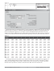
Example: To write a 32-bit value in decimal format.
Note: The closed loop set point of the EZ-ZONE™ PM is contained in two 16-bit registers. Register 2160
contains the two lower bytes (least significant word, LSW) while register 2161 contains the two higher bytes
(most significant word, MSW). The 32-bit answer is an IEEE 754, 32-bit float data type.
42960000 = 75.0 degrees when read as a 32-bit float
0000 4296 is in Low Word, High Word Order.
Register 2160 is written with LSW of 0000 hexadecimal
Register 2161 is written with MSW of 4296 hexadecimal
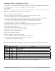
The CRC (also a 16-bit wide value) is sent in reverse order, low byte then high byte.
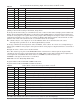
Binary Hex Decimal Purpose
00000001 01 1 Controller Address
00010000 10 16 Function Multiple Write
00001000 08 8 Write Starting at Register High Byte (CLSP is Register 2160 & 2161)
01110000 70 112 Write Starting at Register Low Byte (CLSP is Register 2160 & 2161)
00000000 00 0 Write number of consecutive registers - High Byte (Always 0)
00000010 02 2 Write number of consecutive registers - Low Byte
00000100 04 4 Number of Bytes to Write
00000000 00 00 Data High Byte of 1st register Write - MSB of LSW (consecutive registers)
00000000 00 0 Data Low Byte of 1st register Write - LSB of LSW (consecutive registers)
01000010 42 66 Data High Byte of 2nd register Write - MSB of MSW (consecutive registers)
10010110 96 150 Data Low Byte of 2nd register Write - LSB of MSW (consecutive registers)
00100011 23 35 Low byte of CRC
10000101 85 133 High byte of CRC
Sent to Write (32-bit) Closed Loop Set Point of 75.0
o
F
Table 2.3
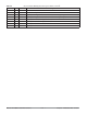
Binary Hex Decimal Purpose
00000001 01 1 Controller Address
00000011 03 3 Function Read
00000100 04 4 Number of data bytes returned
10010111 97 151 Data High Byte of 1
st
register Read - MSB of LSW consecutive registers
01111101 7D 125 Data Low Byte of 1
st
register Read - LSB of LSW consecutive registers
01000010 42 66 Data High Byte of 2
nd
register Read - MSB of LSW consecutive registers
10011100 9C 156 Data Low Byte of 2
nd
register Read - LSB of MSW consecutive registers
01110110 76 118 Low byte of CRC
10010110 96 150 High byte of CRC
Received from the Read Analog Input 1 Process Value 78.204
o
F (32-bit)
Table 2.2