
User`s manual


Watlow EZ-ZONE™ Communications • 15 • Chapter 2 Mobbus RTU & TCP
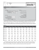
Ethernet Indicator Lights
The PM has four indicator lights on the top of the controller, two of which are not used for Modbus TCP.
The Module Status and Network Status LED’s apply only when EtherNet/IP is enabled. The characteristics
of the Activity and Link indicator lights are defined in the Ethernet specification.
Communications Using Modbus TCP Over Ethernet
Steady
Off
Not powered,
unknown link speed
If the device cannot determine link speed or power is off, the net-
work status indicator shall be steady off.
Red Link speed = 10 Mbit
If the device is communicating at 10 Mbit, the link LED will be
red..
Green Link speed = 100 Mbit
If the device is communicating at 100 Mbit, the link LED will be
green.
Table 2.5
Link Status Indicator
Activity Status Indicator
Table 2.6
Flashing
Green
Detects activity If the MAC detects activity, the LED will be flashing green.
Red Link speed = 10Mbit If the MAC detects a collision, the LED will be red.
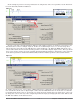
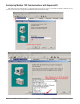
Configuring the PM for Modbus TCP Communications
Prior to establishing communications on the network a valid IP address must be established. There are
two ways in which an IP address can be established: Dynamic Host Configuration Protocol (DHCP, where
a DHCP server on the network provides an IP address); or a fixed IP address (manually entered). The PM
controller's default is set to DHCP. If the PM is brought up on the Ethernet network and there is no DHCP
server present the PM will assume address 169.254.1.1 as the factory default fixed IP address. To change the
fixed IP address or the IP selection method (DHCP or fixed) follow the steps below:
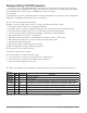
1. Push and hold the up and down arrow keys on the front panel for six seconds to go the the Setup Menu.
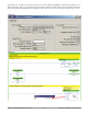
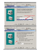
2. Push the up or down arrow key until [`CoM] (Communications Menu) appears in upper display and
[`SEt] in the lower display.
3. Push the green Advance Key ‰ to enter the Communications Menu [`CoM].
4. Push up arrow key to go to the Communications 2 Submenu. The upper display shows [```2], and the
lower display shows [`CoM].
5. Push the Advance Key ‰ until the upper display shows [dhCP] and lower display shows [iP;M]. Use the
up and or down arrow keys to change the addressing method.
6. If [F;Add] is selected above push the Advance Key ‰ and then the up arrow to change the first of four
parts of the IP address. Each part represents a byte which makes up the 32-bit IP address. Follow the
same steps to change each of the other three bytes to complete the IP address.
Note: Excessive writes to the PM may cause premature EEPROM failure. For more detail see the section entitled "Saving
Settings to Nonvolatile Memory".