
User`s manual

Watlow EZ-ZONE™ Communications • 76 • Chapter 2 Mobbus RTU & TCPWatlow EZ-ZONE™ Communications • 76 • Chapter 7 Setup Page
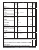
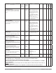
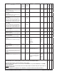
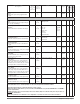
Parameter name
Description
Modbus
(less
40,001 off-
set)
read/write
CIP
class
instance
attribute
Range Default Data
Type
EZ-ZONE™
PM Int.*
EZ-ZONE™
PM PID*
EZ-ZONE™
PM Limt*
Output 1 (digital)
Low Power Scale
The power output will never be less than the
value specified and will represent the value
at which output scaling begins.
896 r/w 106
1
9 r/w
0.0 to 100.0% 0.0% floating
point
XX
Output 1 (digital)
High Power Scale
The power output will never be greater than
the value specified and will represent the
value at which output scaling stops.
898 r/w 106
1
10 r/w
0.0 to 100.0% 100.0% floating
point
XX
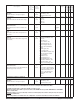
Output 1 (digital)
Power
Monitor the power being supplied to this
output.
894 r 106
1
8 r
0.0 to 100.0% floating
point
XX
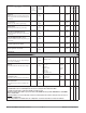
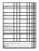
Output 2 Submenu
Output 2 (digital)
Function
Select what function will drive this output.
918 r/w 106
2
5 r/w
Off (62)
Heat (36)
Cool (20)
Alarm (6)
Event (29)
Limit (126)
Heat
Alarm
Off (out-
puts 3
& 4)
integer X X
Output 2 (digital)
Function Instance
Select which source instance will drive the
output.
920 r/w 106
2
6 r/w
1 to 4 1 integer X X
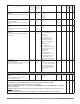
Output 2 (digital)
Control
Set the output control type. This parameter
is only used with PID control, but can be set
anytime.
912 r/w 106
2
2 r/w
Fixed Time Base (34)
Variable Time Base (103)
Fixed
Time
Base
integer X X
Output 2 (digital)
Time Base
Set the time base for fixed-time-base control.
913 r/w 106
2
3 r/w
0.1 to 60.0 seconds (solid-
state relay or switched dc)
5.0 to 60.0 seconds (mechani-
cal relay or no-arc power
control)
0.1 sec.
[SSR &
sw dc]
20.0 sec.
[mech,
relay,
no-arc]
integer X X
Output 2 (digital)
Low Power Scale
The power output will never be less than the
value specified and will represent the value
at which output scaling begins.
926 r/w 106
2
9 r/w
0.0 to 100.0% 0.0% floating
point
XX
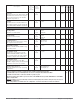
Output 2 (digital)
High Power Scale
The power output will never be greater than
the value specified and will represent the
value at which output scaling stops.
928 r/w 106
2
10 r/w
0.0 to 100.0% 100.0% floating
point
XX
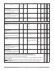
Integers are unsigned, 16-bit values. Floating point values are IEEE 754 32-bit floating point values.
The default Modbus order is Low Word-High Word. The order can be changed in the Communications Menu.
The default serial data format is: 9,600 baud; 8 data bits; no parity; 1 stop bit.
NOTE: Avoid continuous writes within loops. Excessive writes to the EEPROM will cause premature EEPROM failure. The EEPROM is
rated for 1,000,000 writes.
Underlined parameters are not accessable using a remote user's interface (RUI) or the controller's front panel. They can only be ac-
cessed using communications.
*Some of the parameters are not functional in some configurations of each model. Check the user's manual for information.
Int.
PID
Lmt.