
User`s manual


Watlow EZ-ZONE™ Communications • 7 • Chapter 2 Mobbus RTU & TCP
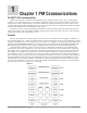
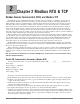
Figure 2.2 & 2.3 Default Assembly Structure
Pointer 21 = 360 & 361
Analog Input 1 Process
Value
Registers 80 & 81
Registers 240 & 241
Registers 82 & 83
Registers 242 & 243
Registers 84 & 85
Registers 244 & 245
Registers 86 & 87
Registers 246 & 247
Registers 88 & 89
Registers 248 & 249
Registers 90 & 91
Registers 250 & 251
Registers 92 & 93
Registers 252 & 253
Registers 94 & 95
Registers 254 & 256
Registers 96 & 97
Registers 256 & 257
Registers 98 & 99
Registers 258 & 259
Value of Pointer 21
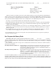
Pointer 22 = 362 & 363
Analog Input 1 Error Status
Value of Pointer 22
Pointer 23 = 440 & 441
Analog Input 2 Process
Value
Value of Pointer 23
Pointer 24 = 442 & 443
Analog Input 2 Error Status
Value of Pointer 24
Pointer 25 = 1496 & 1497
Alarm 1 State
Value of Pointer 25
Pointer 26 = 1546 & 1547
Alarm 2 State
Value of Pointer 26
Pointer 27 = 1596 & 1597
Alarm 3 State
Value of Pointer 27
Pointer 28 = 1646 & 1647
Alarm 4 State
Value of Pointer 28
Pointer 29 = 1328 & 1329
Digital Input 5 Status
Value of Pointer 29
Pointer 30 = 1348 & 1349
Digital Input 6 Status
Value of Pointer 30
Assembly Definition
Addresses
Default Pointers
Assembly Working
Addresses
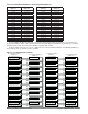
Pointer 31 = 1882 & 1883
Control Mode Active
Registers 100 & 101
Registers 260 & 261
Registers 102 & 103
Registers 262 & 263
Registers 104 & 105
Registers 264 & 265
Registers 106 & 107
Registers 266 & 267
Registers 108 & 109
Registers 268 & 269
Registers 110 & 111
Registers 270 & 271
Registers 112 & 113
Registers 272 & 273
Registers 114 & 115
Registers 274 & 275
Registers 116 & 117
Registers 276 & 277
Registers 118 & 119
Registers 278 & 279
Value of Pointer 31
Pointer 32 = 1904 & 1905
Heat Power
Value of Pointer 32
Pointer 33 = 1906 & 1907
Cool Power
Value of Pointer 33
Pointer 34 = 690 & 691
Limit State
Value of Pointer 34
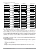
Pointer 35 = 2520 & 2521
Profile Start
Value of Pointer 35
Pointer 36 = 2540 & 2541
Profile Action Request
Value of Pointer 36
Pointer 37 = 2524 & 2525
Active File
Value of Pointer 37
Pointer 38 = 2526 & 2527
Active Step
Value of Pointer 38
Pointer 39 = 2528 & 2529
Active Set Point
Value of Pointer 39
Pointer 40 = 2536 & 2537
Step Time Remaining
Value of Pointer 40
Assembly Definition
Registers
Default Pointers
Assembly Working
Registers
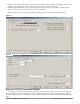
Using a MicroLogix 1200 PLC as the Master - Configuration
Prior to taking a look at some ladder logic examples provided below let’s take a look at the hardware con-
figuration first. This particular control can be purchased with the Modbus RTU protocol and as can be seen
in the screen shots that follow, channel 0 is configured as such. Please note that the hardware configuration
will be different from one control to another. The following screen shots apply to the MicroLogix 1200 control
only. Using the Allen-Bradley 1761-CBL-PM02 cable connecting it to channel 0 of the PLC it is required that
a null modem adapter along with an EIA-232 to EIA-485 converter be used. The output of the EIA-485 con-
verter connects to the EZ-ZONE™ PM slot C (A to CA, B to CB, GND to CC).
In order to establish valid communications between the PLC and the EZ-ZONE™ PM the serial commu-
nications parameters need to match on both ends, PLC and PM. The PM can communicate at 9.6Kb (factory
default), 19.2Kb, or 38.4 Kb with even, odd, or no parity (factory default). To change the PM communication
defaults follow the steps below:
1. Push and hold the up and down arrow keys on the front panel for six seconds to go the the Setup Menu.
2. Push the up or down arrow key until [`CoM] (Communications Menu) appears in upper display and
[`SEt] in the lower display.
3. Push the green Advance Key ‰ to enter the Communications Menu. The upper display shows [Mod],
and the lower display shows [PCoL].
[`CoM].
4. Push the green Advance Key ‰ to change the Modbus address. The upper display shows [1], and the
lower display shows [Ad;M]. Use the up arrow key to change the Modbus address.