
User`s manual


Watlow EZ-ZONE™ RUI/Gateway • 14 • Chapter 5 Networking with a Gateway
Chapter 5: Using an RUI/Gateway
5
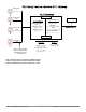
Conceptual View of the RUI Used as a
Gateway:
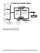
As shown in the following network screen shots the
gateway allows for connectivity between dissimilar
networks. Within the Watlow controls (slaves) there
are many members, of which, some can be read and
some read and or written to such as, the process vari-
able, power output, set points, etc… In order for these
members to be available on the field bus side of the
gateway some basic setup is required in the RUI/Gate-
way. Com instance 1 will always represent the Stan-
dard Bus side where Com instance 2 represents the
field bus side. On each side of the RUI/Gateway there
are addresses (unique to each network) that need to
be set up as well as some network specific settings.
As an example, when using DeviceNet™ as the field
bus of choice the network baud rate and node address
needs to be specified. When using Ethernet the user
can enable EtherNet/IP™, and or Modbus TCP. On
the Standard Bus side the user will determine the
number of EZ-ZONE controllers to scan (starting and
end zones). Once the RUI/Gateway is configured, all
accessible members for each of the EZ-ZONE controls
on the Standard Bus network will be available on the
field bus side of the Gateway.
Using Modbus RTU
(Communications To/From a Master):
Once the gateway instance is enabled for Modbus RTU
there is one other prompt [mof] (Modbus Offset) that
will have an impact on which member is read or writ-
ten to as well as which control.
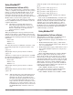
As an example:
Lets assume the offsets are as shown in the graph-
ic on the following page and the master wants to read
the closed loop set point from both Standard Bus ad-
dress 1 and 4. Open up the PM Communications man-
ual then search for closed loop set point. When found,
you’ll notice that the Modbus register that holds the
closed loop set point value is 2160. To read the set
point from Standard Bus address 1 the appropriate
absolute Modbus address would be:
2160 + 400001 + Modbus offset (0) = 402161.
To read the closed loop set point from Standard
Bus address 4 the absolute address would be:
2160 + 400001 + Modbus offset (15000) = 417161.
To learn more about the Modbus RTU protocol as
used with EZ-ZONE controllers go to the Watlow web
site and download the EZ-ZONE PM Communica-
tions User Manual: http://www.watlow.com/literature/
pti_search.cfm
Note: Excessive writes through the gateway to other EZ-ZONE
family controllers may cause premature EEPROM failure. For
more detail see the section entitled “Saving Settings to Nonvola-
tile Memory.”
Note:
[M;oF] as modified through the RUI cannot exceed 9999.
Therefore if it is desired to utilize a Modbus offset as shown in
the graphic below (above 9999) it must be done using EZ-ZONE
Configurator software. This software can be downloaded free of
charge from the Watlow web site, http://www.watlow.com/prod-
ucts/software/zone_config.cfm