RUI/Gateway & DeviceNetTM Configuration & Ladder Logic Example Using an Allen-Bradley CompactLogix PLC Configuring the RUI/Gateway on DeviceNetTM Using RSNetWorx 1. Prior to making the physical connections on the network setup the gateway DeviceNetTM communications parameters per your network requirements, i.e., baud rate and node address. If your not sure how to do this go to http://www.watlow.
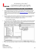
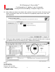
RUI/Gateway & DeviceNetTM Configuration & Ladder Logic Example Using an Allen-Bradley CompactLogix PLC display as shown below. In this particular case, node 7 (RUI/Gateway) appears with a question mark because it has not yet been registered on the network. 5. To register any given node on the network click on Tools and then EDS Wizard.
RUI/Gateway & DeviceNetTM Configuration & Ladder Logic Example Using an Allen-Bradley CompactLogix PLC 6. Select Register an EDS file. 7. Register a single file and then click browse to locate its location.
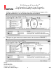
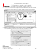
RUI/Gateway & DeviceNetTM Configuration & Ladder Logic Example Using an Allen-Bradley CompactLogix PLC 8. When found notice that if there is an icon with the same name the software will register it along with the EDS file. Click next to proceed with the registration. 9. The next step verifies that there are no errors in the EDS file; a green check should be displayed next to the file as shown below.
RUI/Gateway & DeviceNetTM Configuration & Ladder Logic Example Using an Allen-Bradley CompactLogix PLC 10. After clicking next above, the software will associate an icon to this device, if there was none found in the previous step it will use a default icon to graphically represent this node. Click next to proceed. 11. Clicking next above completes the registration process where the question mark is removed and replaced with the icon of choice for node 7 (Watlow RUI/Gateway).
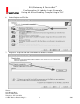
RUI/Gateway & DeviceNetTM Configuration & Ladder Logic Example Using an Allen-Bradley CompactLogix PLC 12. The next series of steps involves mapping the available RUI/Gateway input (84) and output (80) bytes via the scanner into the PLC memory. Double click on the scanner module to proceed. 13. Click on the scanlist tab where the next dialogue will suggest an upload or a download. Click on the upload button to allow the scanner to see what is available on the network.
RUI/Gateway & DeviceNetTM Configuration & Ladder Logic Example Using an Allen-Bradley CompactLogix PLC 14. After the scanner recognizes the RUI/Gateway on the network it will then appear as an Available Device as shown below. Before clicking on the right arrow to add it in the scanners scan list consider the effect of the Automap on Add check box.
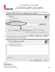
RUI/Gateway & DeviceNetTM Configuration & Ladder Logic Example Using an Allen-Bradley CompactLogix PLC 15. Once the available device (RUI/Gateway in this case) is moved over to the Scanlist the next step will be to map the RUI/Gateway input and output bytes to PLC addresses; first the inputs. In this particular case the Automap on Add box was checked and the result of that now becomes apparent.
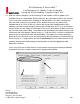
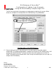
RUI/Gateway & DeviceNetTM Configuration & Ladder Logic Example Using an Allen-Bradley CompactLogix PLC The PLC will need to be in the program or remote program mode for this to occur. When written this completes the configuration of the RUI/Gateway using RSNetWorx. Configuration of the RUI/Gateway 17. Prior to looking at the PLC side of things let’s first take a look at a possible network configuration.
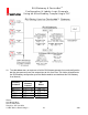
RUI/Gateway & DeviceNetTM Configuration & Ladder Logic Example Using an Allen-Bradley CompactLogix PLC 18. The table below does not represent all of the RUI/Gateway prompts that need configuration but they do represent those that are pertinent to this discussion.
RUI/Gateway & DeviceNetTM Configuration & Ladder Logic Example Using an Allen-Bradley CompactLogix PLC 19. The gateway instance represents the EZ-ZONE® control, in this case, PM 1-4. The enable gateway instance simply turns on that particular gateway where there is a direct correlation between gateway instance 1 and EZ-ZONE® PM controller 1. Likewise, that relationship continues through gateway instance 16 and EZ-ZONE® PM controller 16.
RUI/Gateway & DeviceNetTM Configuration & Ladder Logic Example Using an Allen-Bradley CompactLogix PLC 22. Notice too, the slot number, in this case “1”. This is the physical slot in which the scanner resides. After the scanner is configured two tags will be automatically generated reflecting the existence of the scanner in slot 1 of the I/O structure.
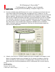
RUI/Gateway & DeviceNetTM Configuration & Ladder Logic Example Using an Allen-Bradley CompactLogix PLC Reading and Writing to/from RUI/Gateway Using RSLogix 5000 24. The rung of logic below when enabled, will execute an explicit message sent to the gateway where it will then be routed out over Standard Bus to the EZ-ZONE® PM control defined by the instance (oSt prompt). Because the CIP offset is set to 12 for gateway instance 4 this message will be routed to PM4.
RUI/Gateway & DeviceNetTM Configuration & Ladder Logic Example Using an Allen-Bradley CompactLogix PLC 25. Notice above that there are screen shots for the configuration and communication tabs. Within the configuration, the programmer will need to specify whether this is a read (Get) or a write (Set) operation as well as the class, instance, and attribute (CIA) of interest. The CIA for all PM controls is 150, 2, 8 respectively.
RUI/Gateway & DeviceNetTM Configuration & Ladder Logic Example Using an Allen-Bradley CompactLogix PLC Default Target to Originator (T to O) Assembly Default Originator to Target (O to T) Assembly Watlow 1241 Bundy Blvd Winona, MN 55987 Telephone: 507-494-5656 © 2007 Watlow Electric Mfg Co 15 4/08
RUI/Gateway & DeviceNetTM Configuration & Ladder Logic Example Using an Allen-Bradley CompactLogix PLC 29. Each of the members shown above are passed implicitly to and from the gateway to the PLC with little to no programming. Note: If you are interested in learning more about how to change either of the implicit assemblies download the PM Communications manual from the Watlow website. Refer to step one for the link to Watlow’s website. 30.
RUI/Gateway & DeviceNetTM Configuration & Ladder Logic Example Using an Allen-Bradley CompactLogix PLC 31. Once the user defined data types have been created for the T to O and O to T assemblies right click on the controller tags folder and add new tags using the T to O and O to T data types just created; in this case, “Custom_GTW_T_to_O” and “Custom_GTW_O_to_T”. Controller Tag (T to O) Controller Tag (O to T) 32.
RUI/Gateway & DeviceNetTM Configuration & Ladder Logic Example Using an Allen-Bradley CompactLogix PLC transfer of data to and from the PLC and EZ-ZONE® controllers via simple copy instructions in the PLC. The copy instruction also works nicely when all of the data types are not the same such as when working with 8 bit, 16 bit, and 32 bit members. The copy instruction copies the source to the destination byte for byte so there is no further conversion needed. 34.
RUI/Gateway & DeviceNetTM Configuration & Ladder Logic Example Using an Allen-Bradley CompactLogix PLC Device Personal Computers RUI Communication Cards EZ-ZONE® Controllers Physical Address 0-3 4-11 12-15 16-31 Logical Address (Set by User) 1-4 1-8 1-4 (indirectly set by user) 1-16 The first graphic in step 35 shows the first member of the custom T to O assembly “GTW_Inputs.Device_Status”. Interpreting the bits…bit 0 is shown on the far right where bit 31 is on the far left.
RUI/Gateway & DeviceNetTM Configuration & Ladder Logic Example Using an Allen-Bradley CompactLogix PLC 37. In step 30 it was suggested that the user may want to create user defined data types. Likewise, in step 31 it was also suggested that the user should create controller tags utilizing those same user defined data types. The reasoning for this may become more obvious in the following example.
RUI/Gateway & DeviceNetTM Configuration & Ladder Logic Example Using an Allen-Bradley CompactLogix PLC Custom T to O Assembly Custom O to T Assembly Watlow 1241 Bundy Blvd Winona, MN 55987 Telephone: 507-494-5656 © 2007 Watlow Electric Mfg Co 21 4/08