
- Watlow RUI/Gateway DeviceNet Configuration Manual


RUI/Gateway & DeviceNet
TM
Configuration & Ladder Logic Example
Using an Allen-Bradley CompactLogix PLC
Watlow
1241 Bundy Blvd
Winona, MN 55987
Telephone: 507-494-5656
© 2007 Watlow Electric Mfg Co 17 4/08
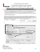
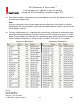
31. Once the user defined data types have been created for the T to O and O to T assemblies
right click on the controller tags folder and add new tags using the T to O and O to T data
types just created; in this case, “Custom_GTW_T_to_O” and “Custom_GTW_O_to_T”.
32. Using the same network architecture as shown in step 17, let’s look closer at the use
of these implicit assemblies. As can be seen above the available 20 members for inputs
and outputs are being distributed across PM1 - PM4 disproportionally. Keep in mind, that the
maximum number of modifiable members for the T to O and O to T assemblies is 20 where
the user can dedicate all of them to one EZ-ZONE
®
PM (*ST excluded) control or distribute
them in any manner across the network. The distribution of the assemblies is determined by
the CIP Assembly size a;nb prompt within the RUI.
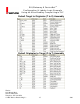
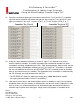
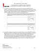
33. Look closely at the names and the descriptions of the assemblies in step 31; the assembly
distribution across the four controls on Standard Bus can be seen clearly. Hopefully it is now
clear as to why it is recommended that user defined data types be created and then the
controller tags to utilize those data types. Simply stated, the purpose is to enable easier
* The EZ-ZONE
®
ST allows for explicit messaging only, it does not allow for implicit
messa
g
in
g
(
communications via the I/O assemblies
)
.
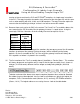
Controller Tag (O to T)
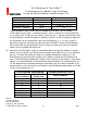
Controller Tag (T to O)