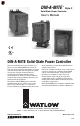
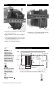
DIN-A-MITE ® Style C Solid-State Power Controller User’s Manual C US LISTED DIN-A-MITE Solid-State Power Controller Please consult this user’s manual when you place your new DIN-A-MITE into service. It contains all the necessary information to mount and wire the product into the application. This manual also contains all user-pertinent specifications and semiconductor fusing recommendations. Refer to national and local electrical code safety guidelines whenever you install electrical equipment.
General Specifications (2365) Operator Interface • Command signal input and indication light • Alarm output and indication light • Current limit indication LED Amperage Rating See the output rating curve chart on page 5 for all the natural convection, fan-cooled, and throughwall mount models. Ratings are into a resistive heater load • Maximum surge current for 16.
Additional Specifications for Contactors and Proportional Controls Control Mode, Zero-Cross • Input Control Signal Type C: VÎ (dc) input contactor. To increase service life, the cycle time should be less than 3 seconds. • Input Control Signal Type K: V~ (ac) input contactor. To increase service life, the cycle time should be less than 3 seconds. • Input Control Signal Type F: 4 to 20 mAÎ (dc) proportional variable time base control.
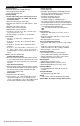
DIN-A-MITE C Ordering Information (2366) To order, complete the code number on the right with the information below: D __ C __ __ - __ __ __ __ - __ __ __ __ __ Style C solid-state power controller Phase 1 = single-phase, 1 controlled leg 2 = 3-phase, 2 controlled legs 3 = 3-phase, 3 controlled legs (use with four wire wye) 8 = 2 independent zones (input control C, K) 9 = 3 independent zones (input control C, K) Current Rating Table Phase Cooling Current at 50°C Cooling and Current Rating Per Leg 0 = Na
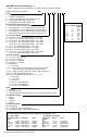
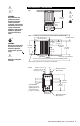
Extended Heater And SCR Life With Variable Time Base Models: DC _ _ -[02, 24, 60] [F0, F1]- _ _ _ _ DIN-A-MITE Style C Ratings at 100% On 90 20% Power, 3 AC line cycles on, 12 cycles off 85 Natural Convection 80 75 50% Power, 3 AC line cycles on, 3 cycles off 70 65 Si as e eg 2-l 40 se, 45 ha leg , 3ase 50 3-p 55 ph le- ng 60 h 3-p Maximum Internal Enclosure Ambient Temperature (°C) Output Rating Curves 35 30 25 0 5 10 15 20 25 30 35 40 45 50 55 60 65 70 75 80 DIN-A-MITE Style C Ra
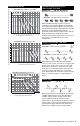
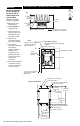
Mount Dismount 4 1 3 2 1 1. Push the unit in and down to catch the rail hook on top of the rail. 1. Press down on the release tab while rotating the unit up and away from the rail. 2. Rotate the bottom of the unit in toward the rail. 3. The rail clasp will audibly “snap” into place. If the DIN-A-MITE does not snap into place, check to see if the rail is bent. 4. Mount the cooling fins vertically.
ç ∫3 Unit Dimensions - Rail-Mounted Top WARNING: Only authorized and qualified personnel should be allowed to install and perform preventive and corrective maintenance on this unit. Failure to follow this guideline could result in damage to equipment, and personal injury or death. 5 WARNING: Hot surface, do not touch the heat sink. Failure to follow this guideline could result in personal injury. 146 mm (5.74 in) 5 Ground wire entry 83 mm (3.25 in) Side 102 mm (4.
Mounting Mounting procedure for UL® 50 Type 4X Enclosure and UL® 1604 Through-wall mount models Materials included: (1) Silicone gasket (8) M5 screws and lockwashers (1) DIN-A-MITE C through-wall Unit Dimensions - Through-Wall (Cabinet Panel) ç ∫3 Top 3. Peel off the protective film from the silicone gasket. Stick the gasket to the heatsink so the gasket holes line up with the screw holes in the heatsink. 114 mm (4.50 in) 55 mm (2.
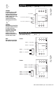
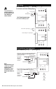
ç ∫1 Input Wiring (For models DC [1, 2, 3] _ - _ _ [C, F, K] _ - _ _ _ _) 1 WARNING: Use National Electric (NEC) or other country-specific standard wiring practices to install and operate the DINA-MITE. Failure to do so may result in damage to equipment and property, and/or injury or loss of life. 3 ∫ WARNING: Only authorized and qualified personnel should be allowed to install and perform preventive and corrective maintenance on this unit.
ç NOTE: The potentiometer is customer-supplied. For the potentiometer only, order Watlow part number 08-5362.
∫1 WARNING: Use National Electric (NEC) or other country-specific standard wiring practices to install and operate the DINA-MITE. Failure to do so may result in damage to equipment and property, and/or injury or loss of life. Input Wiring Phase Angle with Current Limit (Model DC1 _ - _ _ L [0, 1, 2, 3, 4, 5] - _ _ _ _ ) Linear current and linear voltage input 1 Input Signal: 2 ∫ WARNING: Wiring examples show L2 in phase-to-phase, 200 VÅ (ac) and above configuration.
Single-phase Alarm Non-latching Alarm Option DC _ _ - _ _ _ _ - [H, S] _ _ _ NOTE: If you plan to wire multiple DIN-A-MITE alarm outputs, you need to include an intermediate relay for each DIN-A-MITE used.
ç NOTE: Adjust the potentiometer clockwise to increase the current; counterclockwise to decrease the current. 3-phase, 2-leg Shorted SCR Alarm (Model DC2 _ - _ _ [C, F, K, S] _ - S _ _ _ ) 1 7 8 9 10 11 12 13 14 15 16 17 18 19 20 ∫1 WARNING: Use National Electric (NEC) or other country-specific standard wiring practices to install and operate the DINA-MITE. Failure to do so may result in damage to equipment and property, and/or injury or loss of life.
∫2 WARNING: Wiring examples show L2 in phase-to-phase, 200 VÅ (ac) and above configuration. In phaseto-neutral, 100 VÅ (ac) and above applications, L2 is neutral and must not be fused or switched. Failure to follow this guideline could result in personal injury or death. ∫3 WARNING: Only authorized and qualified personnel should be allowed to install and perform preventive and corrective maintenance on this unit.
3-phase, 3-leg Output, Four Wire Wye ç ∫1 ∫2 ∫3 (Model DC3 _ - _ _ _ _ - _ _ _ _ ) Semiconductor Fuses L1 L2 L3 1 7 8 9 10 11 12 13 14 15 16 17 18 19 20 2 3 + + + - Limit Control Contacts (if required) Gain Adjustment Potentiometers Bias ALM Open Heater ALM CT1 CT1 Limit CT2 CT2 Signal Alarm CT3 CT3 Zone 1 Zone 2 Zone 3 4 5 6 Neutral Heater Multizone Output Wiring (For models DC [8, 9] _ - _ _ [C, K] _ - _ _ _ _ 2-zone Line Voltage L1 Semiconductor Fuses 3-zone Semiconductor Fu
ç ∫1 System Wiring Example WARNING: Use National Electric (NEC) or other countryspecific standard wiring practices to install and operate the DIN-A-MITE. Failure to do so may result in damage to equipment and property, and/or injury or loss of life. L3 480 VÅ (ac) L2 L1 Breaker 480 V~ (ac) 120 V~ (ac) ∫2 WARNING: Wiring examples show L2 in phase-to-phase, 200 VÅ (ac) and above configuration. In phase-toneutral, 100 VÅ (ac) and above applications, L2 is neutral and must not be fused or switched.
Ungrounded Delta or Wye Load 3-phase, 2-leg DIN-A-MITE Non-latching Alarm Option (models DC_ _ - _ _ S _ - H _ _ _ ) Open Heater and Shorted SCR Alarm The shorted SCR detector compares the input command signal and actual load current. If load current is present without an input signal then the shorted SCR alarm will energize a triac (on board the DIN-A-MITE) output.
Declaration of Conformity DIN-A-MITE® “C” Power Controller Watlow Winona, Inc. 1241 Bundy Blvd. Winona, MN 55987 USA Declares that the following product: English Designation: DIN-A-MITE® “C” Power Control Model Numbers: DC (1, 2, 3, 8 or 9)(0, 1, 2, 3 or T) – (02, 12, 20, 24, 27, 40, 48 or 60)(C0, C1, C2, K1, K2, K3, F0, F1, S0, S1, S2, S3, S4 or S5) – (0, C, D, H or S)(followed by any 3 numbers or letters.
Required External EMI Filters for DIN-A-MITE with More than 6 A Loads An external EMI filter must be used in conjunction with the DIN-A-MITE for loads in excess of six amperes (6 A) at 150 to 250 kHz. Without a filter applied, the DIN-AMITE does not comply with the conducted emissions standard for loads above 6 A at 150 to 250 KHz. çWARNING: The tank filters specified may suppress desirable communications carried on power lines in the 150 to 250 kHz region.
Warranty Returns The Watlow DIN-A-MITE is warranted to be free of defects in material and workmanship for 36 months after delivery to the first purchaser for use, providing that the units have not been misapplied. Since Watlow has no control over their use, and sometimes misuse, we cannot guarantee against failure.