Microprocessor-Based Auto-tuning Control ( User’s Manual) Watlow Controls, 1241 Bundy Blvd., P.O. 8ox 5580, Winona, MN 55987-5580, Phone: 507/454-5300, Fax: 507/452-4507 W985-MA58-9307 February, 1993 Supersedes: W985-MA70-9043 $10.00 Made in the U.S.A.
How to Use the Manual First.. This manua/ will make your job easier. Reading it and applying the informa- tion is a good way to become familiar with the Series 980/985. Starting Out Chapter 1, Page 4. Install/Wire Chapter 2, Page 6. Front Panel Chapter 3, Page 22. Set Up Chapter 4, Page 24. Tuning Chapter 5, Page 29. Appendix Specifications, Page 34 Cali bration Glossary Warranty An overview: Notes NOTE: Details of a *‘Note** appear here, in the narrow box on the outside of each page.
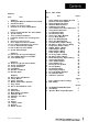
Figures, Table, Charts Chapters page Item 4 4 5 5 Chapter 1 Starting Out With The Watlow Series 980/985 General Description Putting Your Control To Work Overview of the Series 980/985 Menus 6 6 6 6 7 9 9 10 11 13 21 Chapter 2 How To Install And Wire The Series 980/985 System Planning Sensor Installation Guidelines Installation Guidelines For Preventing Noise Noise Checking For Ground Loops Noise Suppression Devices Available..
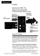
Chapter 1 Starting Out With The Watlow Series 9801985, A Microprocessor-Based Control Single Input Type J, K, T, N or Pt2 Dual OutputsPID or ON/OFF User Selectable Flgure 1 Series 980/985 Input and Output Overview Heat, Cool or Alarm Output 1 or 2 Percent Power Output 1, Heating Auto-tuning General Description Welcome to the Watlow Series 980/985, a dual output, single input, microprocessor-based, 1/8 DIN, auto-tuning temperature control, featuring the Automatic/Manual capability with bumpless transfer.
Putting Your Control To Work To put your Series 980/985 to work, we suggest the following steps: Read the User’s Manual. Plan your installation and wiring. Cut the panel mounting hole and install the control. Wire your Series 980/985 to the system. Start the system and tune the Series 980/985. Make final adjustments to the control parameters and record the data. That’s all there is to it.
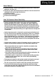
Chapter 2 How to Install and Wire the Series 9801985 System Planning This chapter tells you how to install the Series 980/985. All mounting and wiring information is right here. Because Watlow controls are thoroughly tested and "burned in" before leaving the factory, the Series 980/985 is ready to install when you receive it. But before you begin working, read through this chapter to gain an understanding of the entire installation. Consider sensor installation carefully.
Noise Sources Switches and relay contacts operating inductive loads such as motor, coils, solenoids, and relays, etc. Thyristors or other semiconductor devices which are not zero crossover-fired (randomly-fired or phase angle-fired devices). All welding machinery. Heavy current carrying conductors. Fluorescent and neon lights. How To Decrease Noise Sensitivity Physical separatlon and wire routing must be given careful consideration in planning the layout of the system. For example, A.C.
• Ground loops must be eliminated in the entire control system. There are obvious loops which can be spotted by studying the"as-built" wiring diagram. There are also the not-so-obvious ground loops that result from the technique of connecting internal circuit commons in the manufacturer's equipment. An example of this would be if a control circuit is designed to work with a grounded sensor input. • Do not daisy chain A.C.
"Islatros" and other similar power line filters are designed to carry the power for the control circuit and “buffer” the control circuit from A.C. line noise. Devices like the lslatrol use media (electromagnetic filtering) other than electric circuits to filter out electrical noise. Take care in matching the power capabilities of the filter with power demands of the circuit. Keep line filters as close to the control as possible to minimize the area for interference pick up.
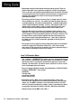
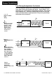
Line Filtering Configurations For Controls Figure 3- These three diagrams show you filter configurations for removing input power noise. Choose the one best suited for your system. For very dirty or critical applications- use a microcomputer-regulated power supply or Uninterruptable Power Supply(U.P.S.) Don’t fasten common mode line filters or filters with metal cases to metal that is at ground potential. This prevents ground loops and maintains filter effectiveness.
How to Install the Series 980/985 Figures 6,7 and 8 provide the Series 980/985’s panel cutout and dimensions. Do not, however, make your panel cutout until you are sure that you are placing the control in the best location. Read the noise guidelines at the beginning of this chapter before installing and wiring the Series 980/985. 1. Place the panel cutout in the desired location. Figure 6 shows you the panel cutout dimensions. 2. To install, carefully insert the Series 980/985 into the panel cutout.
Panel Cutout Max.Panel Thickness 0.50 (12.7mm) Figure 6 Series 980/985 Panel Cutout Dimensions ~ 3.82 +0.03 - 0.00 (92mm + 0.8) Load Power indicators V T I .89 (48.
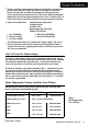
How to Wire the Series 980/985 The Series 980/985 wiring is illustrated by model number option. Check the unit sticker on the control and compare your model number to those shown here and also the model number breakdown in the back of this manual. Series 980/985 internal circuits appear “inside“ the line drawing of the 980/985, while connections and terminal designations appear “outside” the line drawing. All outputs are referenced to a de-energized state.
lnput Options “1“, “2” & “3”, Thermocouple Input Terminals 18 & 20 Figure 10 Input Options “1”, **2* & *3’, Thermocouple Wiring Diagram. I Model # 98– A - 1 _ _ - 0-0000 98_A-2 – – 0-0000 98_A-3- – – 0-0000 II II 1 NOTE: You must use an isolated or ungrounded thermocouple if an external 4-20mA output device with a non-isolated circuit common is connected to the 4-20mA output. Extenslon wire for thermocouples must be of the same alloy as the thermocouple itself to limit errors.
Input Options “2” & " 3 " RTD - 2 Wire Terminals 12 - 14 ModeI#98 _ A - 2 _ _0-0000 98_A-3_ _0-0000 Figure 12 Input Options "2" & “3”, RTD (2 wire) Sensor Wiring. Jumper#l3to#l4 II II . . . . . . Input Options “2” & " 3 " RTD - 3 Wire Terminals 12 - 14 Model# 98_A-2_ _ 0-0000 98_A-3_ _0-0000 Figure 13 Input Options “2’ & ‘*3”, RTD (3 wire) Sensor Wiring. . . . . . . J NOTE: Long lead lengths create electrical resistance.
Output 1 Option “B”, Solid State Relay ModeI# 98_A-_ B _0-0000 Figure 14 - Solid State Relay, Output 1, Option “B” Wiring Diagram. Solid State Relay Solid State Relay Watlow's solid state relays change state at zero volts, which is *zero-cross switching.” They are also optically isolated, which means the output circuitry is energized by infrared light striking a photo-sensitive device. This results in virtual absence of electrically generated noise, pIus output to input electrical isolation.
Output 1 Option “D”, 6 Amp Mechanical Relay Model#98_A-_D _0-0000 Figure 16 - Mechanical Relay 6 Amp mechanical Relay, Output 1, Optlon “D” Wlrlng Diagram. Mechanical Relay The Electromechanical relay iS an electrical and mechanical d8vice with moving parts. When power is applied to the relay solenoid, Contact closure is Created through movement of the “Common” Contact of the relay. Off state impedance is 2OK ohm minimum.
Output 1 Option “F", 4-20mA Model# 98_A-_F _0-0000 Figure 18 4-2OmA, Output 1, Option "F" Wiring Diagram. Process Output Proportional value determined by the control to balance the sensor input and set point. This value will fall between 4-20mA depending on your process output type. Output 1 Option “G”, O-20mA Model# 98_A-_G _0-0000 Figure 19 0-20mA, Output 1, Option “G” Wiring Diagram. Process Output Proportional value determined by the control to balance the sensor input and set point.
Output 1 Option “H”, O-5VDC Model# 98_A-_H _0-0000 Figure 20 O-5VDC, Output 1, Option "H" Wiring Diagram. Process Output Proportional value determined by the control to balance the sensor input and set point. This value will fall between O-5VDC dependlng on your process output type. Output 2 Option “B”, Solid State Relay Model# 98_A- - - B 0-0000 Figure 21 S.S. Relay, Output 2, Option "B" Wiring Diagram.
Output 2 Option “C", DC Output (Open Collector) Model# 98_A- __ C 0-0000 . . . . . . . Figure 22 DC Output (Open Collector), output 2 Option "C" Wiring Diagram. ’ 9 - 8 Heat, Cool + # or Alarm Switched DC Watlow’s solid state switch is a low current DC output (open collector) used to switch an external power switching device such as a SSR or an electromechanical relay. The input specifications of the power switching device must match those listed for the SS switch output.
n T WARNING: Install high or low temperature limit control protection in systems where an overtemperature fault condition could present a fire hazard or other hazard. Failure to install temperature limit control protection where a potential hazard exists could result in damage to equipment and property, and injury to personnel. 0 0 1 CAUTION: Do not jumper load power from the control power terminals. Doing so will cause your control to be more susceptible to electrical interference from loadswitching.
Chapter 3 How to Use the Keys and Displays Series 980/985 Displays and Load LED’s Upper Display Red, 0.3” high LED, seven segment, three or four digit display indicating either process actual temperature, the operating parameter values, or an open sensor. 1 NOTE: The Upper display will always show the process value after 1 minute without key strokes. Figure 25 Series 980/985 Displays Lower Display / Red 0.
Series 980/985 Keys Figure 27 Series 980/985 Keys UP/DOWN keys When pressed simultaneously for 3 seconds, the Setup Menu appears displaying the LOC parameter. From the LOC parameter, press the UP/DOWN keys again and the Calibration Menu appears. MODE Key Steps the control through the Operating menu; also, in the Auto mode, enters new data selected less than 5 seconds previously . el Increases the value of the displayed parameter. A light touch increases the value by one.
Chapter 4 1 NOTE: While in the Setup menu, all outputs are OFF. How To Setup The Series 9801985 Setting up the Series 980/985 is a simple process. First configure the 980/ 985’s features to your application in the Setup Menu, and then enter values in the Operating Menu. Both tasks use the MODE key to move through the menus and the UP/DOWN keys to select data. Entering the Setup Menu The Setup Menu displays the parameters that configure the Series 980/985’s features to your application.
Setup Parameters At the top of the menu, the Series 980/985 displays the user level of operation in the Upper display, and the LOC parameter in the Lower display. When pressing the MODE key, the value of the next parameter appears in the Upper display, and the parameter itself is in the Lower display. Lock: Selects the level of operator lock-out. This parameter’s range is from 0 - 3. The default is 0.
Latching: Selects whether the output is latching or non-latching when Output 2 is an alarm. Latching alarms must be cleared before the alarm output will reset. Non-latching automatically resets the alarm output when the condition clears. The range is LAt or nLA, default is nLA. This only appears if the Ot2 = AL. Silencing: Selects alarms silencing (alarm inhibit). Appears only when ALt = dE. If LAt, press the Auto/Man key to reset the alarm output.
m Mode Key J NOTE: The Upper display will always show the process value after 1 minute without key strokes. + Control Set Point 1 g.f$fygj [!I=. Prompt appears or not according to control configuration. Figure 29 The Operation Menu. Operation Parameters Set Point 2: Sets the operating set point for Output 2 when control mode is Ht/ Ht or CL/CL. SP2 only appears when Ot1 and 0t2 are the same, and functions as an ON/OFF control.
Dead Band: Enter the Dead Band between the heating and cooling functions adjustable from ± 99°F/± 55°C. The default is 0°. Appears when Ot2 = CL. Alarm Low: Represents the low process alarm or low deviation alarm. Displayed only when 0t2 parameter is AL. Alarm High: Represents the high process alarm or high deviation alarm. Displayed only when Ot2 parameter is AL. Calibration Offset. The range is ±99°F/±55°C. The default is 0°. Calibration Offset adds or subtracts degrees from the input signal.
Chapter 5 How to Tune and Operate Tuning - Automatic Auto-tuning: The Series 9801985 gives you the capability to automatically tune the PlD parameters to fit the characteristics of your particular thermal system. The auto-tuning procedure operates on a thermal response value - slow, medium, or fast. A slow thermal response is used when the process temperature is not met too rapidly, or greatly exceeds the set point value.
Tuning - Manual For optimum control performance, tune the Series 985 to the thermal system The tuning settings here are meant for a broad spectrum of applications; your system may have somewhat different requirements. 1. Apply power to the Series 965 and enter a set point. Begin with these Operation Parameters: Pbl = 1, rE1 = 0.00, rA1 = 0.00, Ct1 = 5, CAL = 0, AUt= 0. 2. ProportionaI Band Adjustment (Output 1): Gradually increase Pb1 until the Upper display temperature stabilizes to a constant value.
Indication of Auto/Manual operation is the LED located on the AUTO/MAN key. When the LED is ON, the control is in the Manual operation, an alarm condition is present, and the output de-energizes. When the LED is OFF, the control is in AUTO operation and the alarm is energized. When the LED flashes, press the key again within five seconds to complete the change in operation.
•If the alarm is non-latching... The alarm will clear itself automatically as soon as the process temperature is inside the alarm limit by 3°F/l.7°C for 1° RTD units, or 0.3°F/0.17°C for 0.1° RTD units. A 1 CAUTION: An alarm display will be masked by an error condition or when the control is in the Calibration or Set Up Menus. l How To Deal With Error Codes J’ Press ~ twiceRead error Three dashes, “- - -", in the upper display indicate a Series 985 error. l If operator access is LOC 0 or 1 . . .
Er 1, 2, 3 & 7 Errors - Control Outputs May Be ON If operator access is LOC 0 or 1 . . . . ..and the control was in AUTO operation when the error occurred, it will go into MANUAL (% power) operation. If the output power is less than 70%±5% change within the last two minutes, the 985 will switch into Manual operation at the last Automatic power level. If the control was in MANUAL operation, it will remain there. (You must press the AUTO/ MAN key twice to see the error code.
Appendix Control Mode • l l Single set point, non-ramping. Single input, dual outputs. Control outputs: User selectable as: Heat, Heat/Heat, Heat/Cool, Cool, Cool/Cool, Heat/Alarm, Cool/Alarm Outputs independent, or related via deadband for Heat/Cool. ON/OFF: 3°F or 1.7°C switching hysteresis or 0.3°F or 0.l7°C for 0.10 Units . PID parameters: Proportional band: 0 to 999°F/0 to 555°C(3 digit only) 0 to 999°F/0 to 555°C or 0 to 99.9°F/0 to 55.5°C (3 or 4 digit) Reset: 0.00 to 9.99 repeats per minute.
Primary Output (Heating or Cooling) Solid state relay, 0.5A @ 24VAC minimum, 253VAC maximum, optoisolated, zero cross switching. Electromechanical relay, Form C, 6A @ 115/230VAC, 6A @ 28VDC, 1/8 hp. @ 115VAC 125VA @ 115VAC. Warranted to 100,000 cycles. Open collector, switched DC signal provides a minimum turn ON voltage of 3VDC into a minimum 500 ohm load, maximum ON voltage not greater than 32VDC into an infinite load. 4-20mA reverse acting into a 600 ohm maximum load.
Series 980/985 Model Number Information The Series 980/985 Model Number, listed on your unit sticker, is defined below. ,918 ‘ Control Series 980/985 = Dual output, microprocessor-based I/8 DIN Mounting 0 = Horizontal 5 = Vertical Input 1 2 3 , = Type J thermocouple (3 digit only) = Type J, K, T, N, PT 2 thermocouple; RTD 1°, 420mA, 0-5VDC (4 digit) = Type J, K, T, N, PT 2 thermocouple; RTD 0.1°, 4-20mA, 0-5VDC (4 digit) #1 output B = Solid state relay, Form A, 0.
Calibration Menu n? l In the Calibration Menu, various input signals must be supplied in order for the control to go through its auto calibration. The calibration menu can only be entered from the LOC parameter in the Setup menu. Press the UP/DOWN keys simultaneously for 3 seconds (± 1 second). The CAL parameter appears. CAUTION: Incorrect calibration will affect the accuracy and should only be attempted with proper equipment and by qualified personnel. Figure 33 Entering the Calibration Menu.
tcL Thermocouple, low end uncompensated. 0 mV tcH Thermocouple, high end uncompensated. 50mV Thermocouple compensated value reference. RTD low end resistance, see Table 2 on Page 39. RTD high end resistance, see Table 2 on Page 39. Figure 34 The Calibration Menu. t Process input. 0V Process input. 5V Process input. 4mA A 4A0 Process input. 20mA t Process output. 4mA Process output. 20mA Restore factory calibration values. See Page 37. Factory use only. Factory use only.
RTD Field Calibration Procedure Equipment Required l 1K ohm precision decade resistance box with 0.01 ohms resolution. Setup And Calibration ar NOTE Before calibration on an installed control, make sure all data and parameters are documented. See Setup and Operation Charts, Pages 26 and 28. 1. Connect the AC line voltage L1 to Terminal #4, L2 to Terminal #7, and Ground to Terminal #8. Jumper for correct line voltage. See Chapter 2. 2.
0 - 5 Volt Field Calibration Procedure Equipment Required l Precision voltage source 0-5 volt minimum range with 0.001 volt resolution. Setup And Calibration J-3 NOTE: Not all parameters will appear. They are dependent on your unit type. Use only the steps that apply to your unit. aI NOTE Before calibration on an installed control, make sure all data and parameters are documented. See Setup and Operation Charts, Pages 26 and 28. 1.
4-20mA Input Field Calibration Procedure Equipment Required l Precision current source 0-20mA minimum range with 0.01 mA resolution. Setup And Calibration J 1 NOTE Before calibration on an installed control, make sure all data and parameters are documented. See Setup and Operation Charts, Pages 26 and 26. 1. Connect the AC line voltage Ll to Terminal # 4 , L2 to Terminal #7, and Ground to Terminal #8. Jumper for correct line voltage. See Chapter 2. 2.
0-20/4-20mA Output Field Calibration Procedure J3 NOTE Not all parameters will appear. They are dependent on your unit type. Use only the steps that apply to your unit. Equipment Required l l 470 ohm 1/2 watt 10% resistor. 4 - 1/2 digit Digital Multimeter. Setup And Calibration J NOTE Before calibration on an installed control, make sure all data and parameters are documented. See Setup and Operation Charts, Pages 26 and 28. 1.
0-5/0-10 Volt Output Field Calibration Procedure Equipment Required l l R NOTE: 20K ohm, 1/4 watt, 10% resistor 4 - 1/2 digit Digital Multimeter. Not all parameters will appear. They are dependent on your unit type. Use only the steps that apply to your unit. Setup And Calibration 1 NOTE Before calibration on an installed control, make sure all data and parameters are documented. See Setup and Operation Charts, Pages 26 and 26. 1.
Droop: Difference in temperature between set point and stabilized process temperature. Alarm: A condition, generated by a controller, indicating that the process has exceeded or fallen below the set or limit point. Duty cycle: Percentage of “load ON time” relative to total cycle time. Anti-reset: Control feature that inhibits automatic reset action outside of the proportional band. Hysteresis: In ON/OFF control, the temperature change necessary to change the output from full ON to full OFF.
PD control: Proportioning control with rate action. Switching sensitivity: In ON/OFF control, the temperature change necessary to change the output from full ON to full OFF. PI control: Proportioning control with auto-reset. PID control: Proportioning control with autoreset and rate. Process varlable: Thermal system element to be regulated, such as time, temperature, relative humidity, etc.
A Appendix , 34 AUTO/MAN key, 23 Automatic Operation, 23,31 Auto-tuning, 30 B Bumpless transfer, 31 C Calibration, 38 Combination Differential Filter, 10, Fig. 5 Common Mode Fitter Wiring, 10, Fig 4 D DCOutput 1, 16, Fig.16 DC Output 2,20, Fig. 20 Decrease Noise Sensitivity, How To, 7 Default Parameters, Installation, 26, Chart 1 Operation, 28, Chart 2 Differential Mode Filter Wiring, 10, Fig. 3 Dimensions, Control, 12, Fig. 7 Panel Cutout, 12, Fig.
Warranty The Watlow Series 980/985 is warranted to be free of defects in material and workmanship for 36 months after delivery to the first purchaser for use, providing that the units have not been misapplied. Since Watlow has no control over their use, and sometimes misuse, we cannot guarantee against failure.